Applies To These Products
QCL500 OEMQCL500 OEM(+)
QCL1000 OEM
QCL1000 OEM(+)
QCL1500 OEM
QCL1500 OEM(+)
QCL2000 OEM
QCL2000 OEM(+)
Question
What power supply should I use with the QCL OEM Driver?
Answer
The QCL OEM and QCL OEM(+) drivers require two power supplies – one positive and one negative. The WEI part number is PWRPAK-24V.
Wavelength offers standard 24 V switching power supplies. These provide up to 16 V compliance voltage to the Quantum Cascade Laser (QCL).
For lower compliance voltage, request PV048. Adjust the same power supplies to 19 V to provide a compliance voltage of 11 V to the QCL.
For higher compliance voltage, request PV055. Adjust the same power supplies to 28 V to provide a compliance voltage of 20 V to the QCL.
To wire the power supplies, follow the instructions in the datasheet:
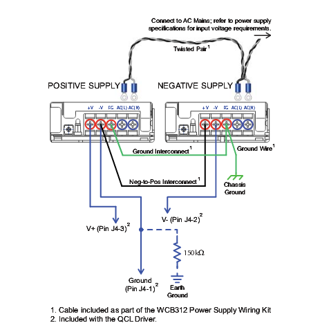
Wire the QCL driver to the dual power supplies as shown above. If you are using the PWRPAK-24V power supplies from Wavelength, we recommend you also use the wiring kits WCB312 and WCB313.
Follow these instructions to wire the power supplies using the WCB312 and WCB313. The same method applies to connect other power supplies to the QCL driver.
- The AC Line (black) and Neutral (white) wires: 24 AWG black and white wires, 10″ with ring lugs unattached but included in kit: connect the AC Line wire to the AC(L) terminals and the Neutral wire to the AC (N) terminals, as shown.
- AC Safety Ground #1: 24 AWG green wire, 10″ with ring lugs on each end; connect to the Frame Ground terminals on the power supplies.
- AC Safety Ground #2: 24 AWG green wire; 10″ with one ring lug; connect to the Frame Ground terminal on one power supply; connect the other end to Earth Ground (usually through the equipment rack, chassis, or optical bench).
- Common Ground: 24 AWG black wire; 10″ with ring lugs on each end; connect between V- of Positive Supply and V+ of Negative Supply.
- Use the remaining ring lugs to connect the power supply cable (WCB313) to the V+, Power Ground, and V- terminals of the power supplies. See cabling section of datasheet for information on the WCB313 cable.
The figure above indicates a 150 kΩ resistor connecting the power supplies to ground; this resistor is necessary if the electronics ground is tied to earth ground at some point within your system, such as at a DAQ card, computer, or USB cable connection.
This resistor provides a lossy connection from system ground to earth ground, and will prevent the ground potential of isolated power supplies from drifting. NOTE: Some systems can have problematic ground loops. If this occurs, you may want to try and optically isolate the remote POWER and ENABLE lines. It is not a requirement for low noise operation, but it can be an option.
NOTE: For remote operation the front panel Power and Enable switches must be on.
If you are unsure whether to include this resistor in your system, contact Wavelength Electronics for technical assistance.
