Question
How do I wire my Quantum Cascade Laser (QCL)?
Answer
First, review the QCL datasheet to determine which pin current flows into and which pin current exits from. Here is an example from a Hamamatsu datasheet:
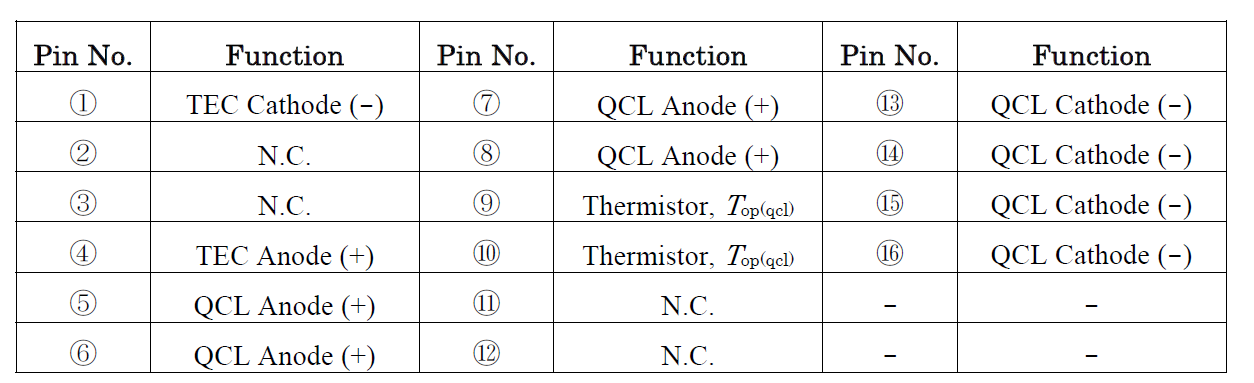
Anode is the input pin (here pins 5, 6, 7, & 8).
Cathode is the output pin (here pins 13, 14, 15, & 16).
Next, determine if either input or output pin is tied to the case.
- If neither side is tied to case, for highest bandwidth, use the QCL OEM or QCL LAB original current driver.
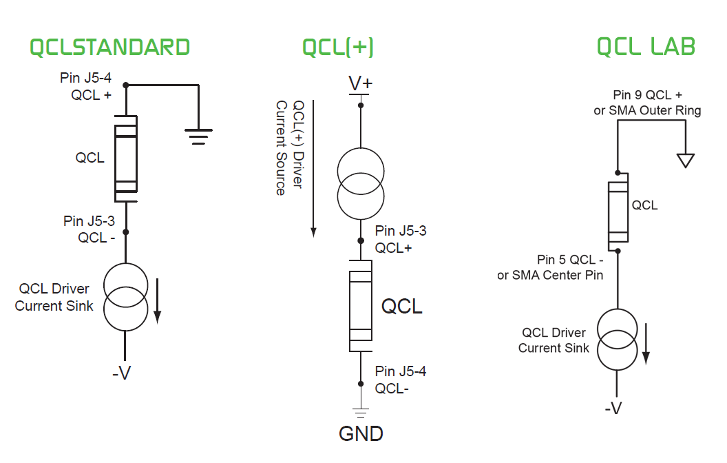
- On the OEM unit, wire the input to pin J5-4 and the output to pin J5-3 as shown below. The QCL OEM will act as a current sink and the QCL input pin will be internally grounded.
- On the LAB unit, wire the input to DSUB Pin 9 or the SMA Outer Ring. Wire the output to DSUB Pin 5 or the SMA Center Ring.
- If one side is tied to case, decide if the case will be grounded or left to float electrically.
- If one side is to be grounded, choose the QCL Standard or QCL(+) to ground the proper end. See the diagrams below.
- If the case will float, for highest bandwidth, use the QCL OEM or QCL LAB original current driver.
Eliminating ground loops in other parts of the system is critical to achieve the low electronic noise of these drivers. Refer to AN-LD08: Manage Ground Loops to Minimize Noise with the QCL Drivers or AN-LD09: Troubleshooting Low Noise Systems for more information.
