Applies To These Products
HTC1500HTC1500-62
HTC3000
HTC3000-62
HTC4000-62
PID1500
WLD3343
WLD3343-2L
WLD3343HB
WLD3343-3A
WLD3343-3L
Question
How do I install a remote Enable/Disable Switching Circuit?
Answer
Some temperature controller and laser diode driver components have remote Enable and Disable capability designed in with the current limit functionality. The user usually adds a simple on-off switch. This can be implemented with a simple switch across the limit inputs such that
open = output current enabled and closed (shorted) = output current disabled.
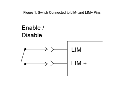
To add a simple enable/disable switch, connect it to the LIM + and LIM- pins as shown in Figure 1.

By shorting the LIM+ and LIM- pins, the output current is disabled. Leaving the pins open, the output current is enabled up to the maximum capacity of the controller.
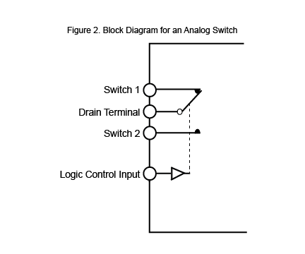
A more sophisticated switching method may be needed when the output needs to be controlled by a computer or other remote circuit. This requires either a relay or analog switch such as Figure 2.

When connecting the analog switch to the LIM pins, use the following table to determine the output status:
| Logic Control Input | Output Status |
|---|---|
| Connect LIM+ to Drain Terminal Connect LIM- to Switch 1 |
|
| 0 | Enabled |
| 1 | Disabled |
| Connect LIM+ to Drain Terminal Connect LIM- to Switch 2 |
|
| 0 | Disabled |
| 1 | Enabled |
The benefits of using an analog switch, such as the ADG436, rather than a relay for more complex situations are that it is more energy efficient (uses µA rather than mA), is smaller, and is less expensive.
Using Resistors to Set a Safety Current Limit
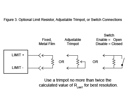
If a resistor is used in parallel with the switch or relay, a safety current limit can be set. Figure 3 below shows the different resistor and switch configurations that are possible for Wavelength’s products.

If quicker switching is required, a MOSFET circuit may be used. Contact your Wavelength Sales Engineer for more information.

