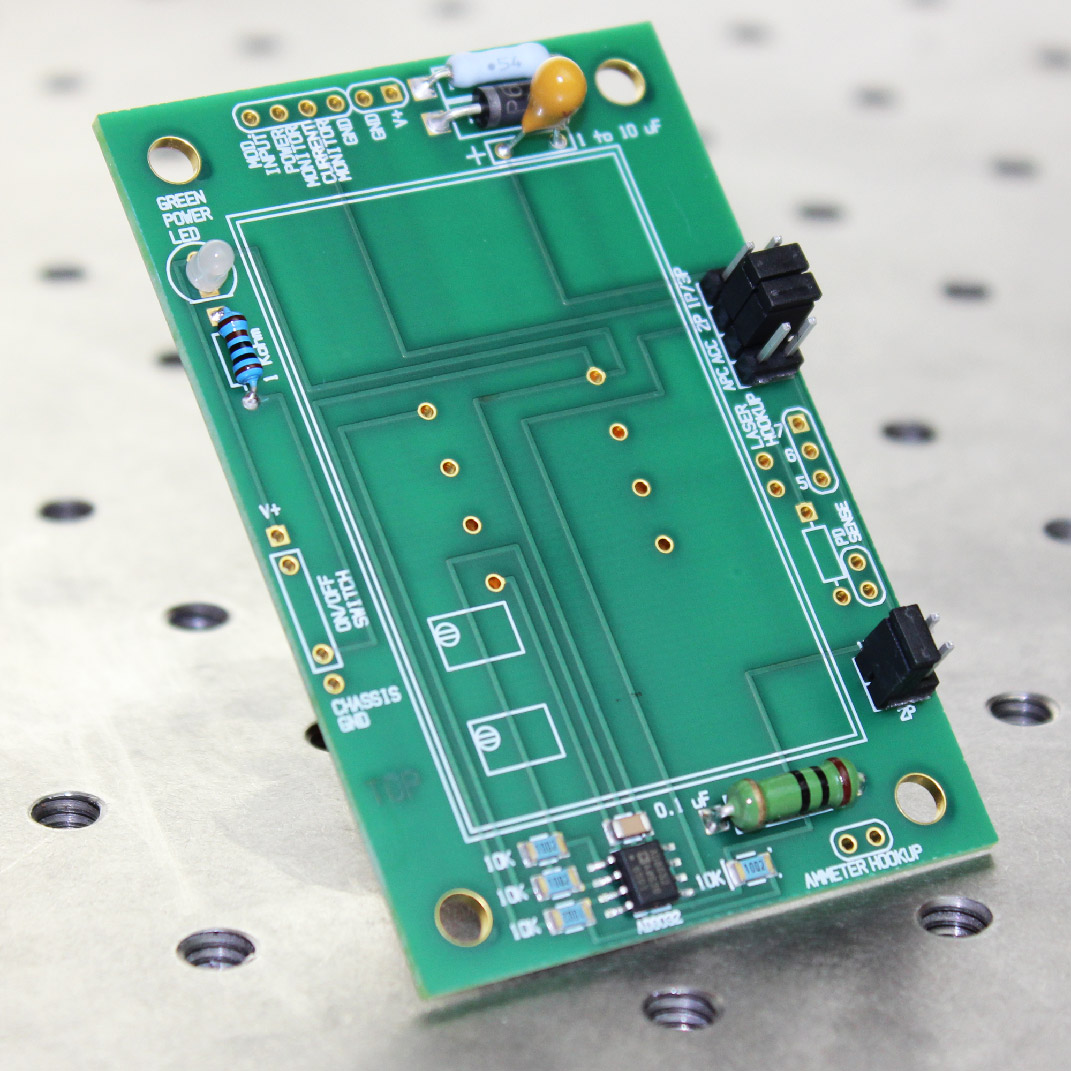
The LDDEVALP evaluation board supports the LDD200 P or LDD400 P series Laser Diode Drivers. Two jumpers set up for Type A, B, or C laser diodes. A power LED indicates when power is connected to the board. A transzorb protects against over-voltage.
A cable for TO-3 laser diodes is available (P/N: WCB201).
Free, effective, and responsive technical support is available to simplify integration of Wavelength products into your OEM design. Standard product can be easily modified to meet your application requirements.
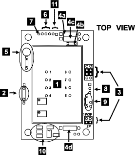
Top View of LDD P Series Evaluation Board

1- LDD Module – location of Laser Diode Driver component
2- Enable / Disable wire pads – Signal input to enable or disable laser diode current
3- Jumpers – select which LDD model is installed
4a- Decoupling Resistor – Decouple the power supply
4b- Decoupling Capacitor – Decouple the power supply
4c- Transzorb – Over-voltage protection
4d- Dominant Impedance – Laser Diode over-current and transient protection
5- LED and bias resistor – Power ON indicator
6- Measurement wire pads – Measure laser diode current
7- MOD INPUT wire pads – Connect to optional signal generator for modulation or remote setpoint control
8- Laser diode wire pads – Solder laser diode cable to these pads
9- External photodiode wire pads – Monitor photodiode current while in constant laser diode current mode
10- Op-amp, four resistors, one capacitor – For operating LDD 2P in constant current mode
11- Power supply wire pads – Connections to power supply


