SIMPLIFIED PROTOTYPING
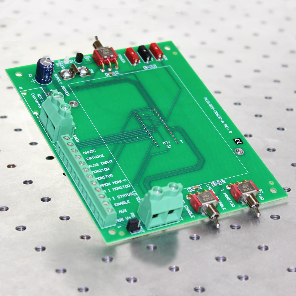
Use the PLD10EV Evaluation Board to rapidly prototype a complete high power laser diode control system using the PLD10000 or PLD12500. The PLD10EV makes it easy to set up, operate, and familiarize yourself with the PLD driver when you’re prototyping your control system, and makes it easier for you to integrate your final design.
UNBEATABLE CONVENIENCE
Onboard switches, power supply configuration jumpers, and probe-ready test points simplify your setup and configuration tasks, and will have the PLD up and running in minutes.
The PLD10EV board includes high-current screw terminals to connect the power supply and laser diode. The low-current screw terminals allow direct access to all the pins and functions of the driver, so you can directly mock-up your control system.
It is CE certified. A PDF version of the Declaration of Conformance is available.
The PLD driver is ordered separately.
Free, effective, and responsive technical support is available to simplify integration of Wavelength products into your OEM design. Standard product can be easily modified to meet your application requirements.
Size: 4.5″ x 5.5″ x 2.75″ (with PLD10000 or PLD12500 installed)
114 x 140 x 70 mm
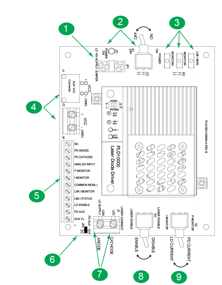
Top View of PLD10EV

1. Power Supply Shorting Bar – Install jumper to tie +5V pins (13,14,15) to +LD Supply pins (7,8,9).
2. Power On – This switch applies DC power to the PLD10000 or PLD12500. The Green LED will light when DC power is applied.
3. Test Points – Test points allow you to monitor Limit Current and either Laser Diode or Photodiode Current based on the Monitor Switch position.
4. Power Supply Input – This two pin terminal strip is for +5 V input. We recommend 14 AWG wire. Pads for custom connector installation.
5. Screw Lock Connector – We recommend 22 AWG wire to these inputs and monitors.
6. Laser Type-C Jumper – This jumper is used with Type C laser diodes only. By default it is not installed at the factory. Install ONLY for Type-C Lasers (default shown here — Type A/B Lasers)
7. Laser Connection – We recommend 14 AWG wire.
8. Output Current – Once DC power is applied, this switch either enables or disables laser diode current. Toggle this switch to clear a Current Limit error.
9. Monitor Select – Monitor Limit Current and either Laser Diode or Photodiode Current based on the Monitor Switch position.


