Question
We are using the WLD with a C-mount 2 W 808 nm diode, and questions about how to handle the laser and controller. What handling precautions do you recommend? And what should we be concerned about when we’re configuring the driver with the laser?
Also, we want to make sure we’re minimizing current noise to the laser. Do you have any recommendations for noise and transient suppression filters?
Answer
You raise good questions, so we’ll cover handling precautions and then we’ll discuss filters.
Handling Precautions
- First and foremost, always take care to prevent ESD damage to the laser and electronic components by following appropriate ESD handing precautions. This website is a good place to learn about ESD:
https://aetd.gsfc.nasa.gov/560/index.php/ESD_BestPractices.html - We recommend you initially set up the WLD using one a test load. More information regarding test loads can be found on the Test Loads Basics page.
- Make sure that all electrical connections are firm. An intermittent connection will cause a laser to fail immediately because of the voltage spike that is delivered as the broken connection is remade.
- Set the limit and drive current according to the datasheet that came with your laser.
- Properly heat-sink and temperature control the laser.
- Do not switch the WLD3343 from Constant Current mode to Constant Power mode while the unit is powered on.
- Placing electronic measurement equipment in the output circuit must be done very carefully. Follow these safe handling precautions to help prevent damage to the laser:
- Never place an ammeter in series with the laser diode.
- Never place a voltmeter in parallel with the laser diode.
- If you want to measure the actual current through the laser, place a low-value resistor in series with the laser and measure the voltage drop across the resistor. Then calculate the current using Ohm’s Law (I = V / R). You can use a 1 Ω resistor, or a larger value if there is sufficient head-room on the driver compliance voltage.
- If you place any electronic measurement devices in the output circuit, do not let them auto-range. When meters switch ranges they can introduce transients and instabilities that may cause unpredictable behavior. Likewise if you find you need to manually range a meter, switch off the output of the laser driver first.
Filters
Regarding filters for noise and transient suppression, there are some simple circuits that may be beneficial. Two circuits are presented here, though they just touch the surface of filter design.
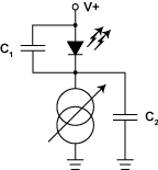
Transient / ESD Filter
Adding capacitors in the output circuit will affect the bandwidth of the system if you are modulating the laser. Capacitor value selection should take into consideration the dynamic resistance of the laser diode and capacitor, and is a design task more involved than can be discussed here.
This ESD / Transients filter will help suppress noise from the current source and power supply. Capacitor C1 across the laser diode will help with a noisy power supply; C2 will help with a noisy current source. Use a ceramic or teflon 0.1 µF capacitor.
 |
When using capacitors in this manner you must take care with other design parameters. For example, lengthy leads add inductance to the circuit, and will combine with the capacitors to make an oscillator. Minimize the lead-length to reduce the added inductance.
Power Supply Over-Current Filter
The third filter provides power supply transient suppression, and the resistor provides additional protection from power supply over-current faults.
 |
Again, use a ceramic or teflon 0.1 µF capacitor. The resistor acts as a current limiter to protect the laser diode in case of power supply over-current faults; calculate the resistor value using this equation:
RLIM = (V+ – VLD – VI.DROP) / ILIM
V+ = Power supply voltage
VLD = Voltage drop across the laser diode at the current limit
VI.DROP = Voltage drop across the current source
ILIM = Laser drive current limit
The resistor must be sufficiently power rated in case of a power supply or current source fault. Calculate the power dissipation using this equation, and choose an appropriately rated resistor:
P = ILIM2 × RLIM
There are far more advanced output filters that can be applied to reduce ESD effects and electrical noise, but such circuit design is beyond the scope of this FAQ.
