What is a QCL?
Quantum Cascade Lasers (QCLs) are semiconductor lasers that emit in the mid- and long-wave IR bands, and are finding new applications in precision sensing, spectroscopy, medical, and military applications(1). Their wide tuning range and fast response time allow for faster and more precise compact trace element detectors and gas analyzers that are replacing slower and larger FTIR, mass spectroscopy, and photothermal microspectroscopy systems.
This diagram represents the physics behind Quantum Cascade Lasers.
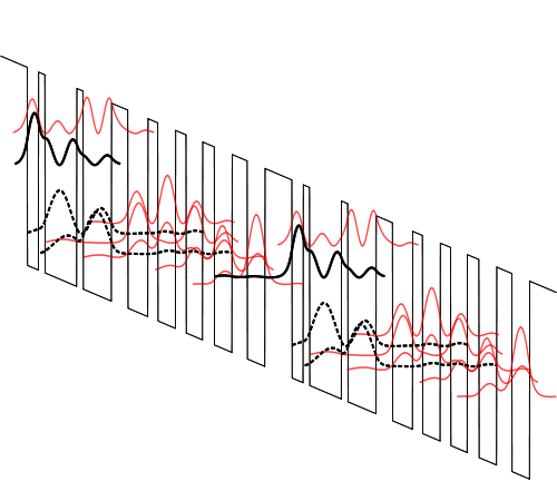
Figure 1: Quantum Cascade Laser Energy Band Diagram, Simplified
For more information about QCLs and the physics behind them, visit our QCL Basics page.
What is a QCL Driver?
A quantum cascade laser driver is similar in some respects to drivers used for semiconductor laser diodes, but there are important differences that make it worthwhile to find the proper QCL driver for your application. Choosing the wrong driver may make high-precision applications impossible, or put at risk a very expensive and difficult-to-source quantum cascade laser.
| Symbol | Name & Brief Description |
|---|---|
 |
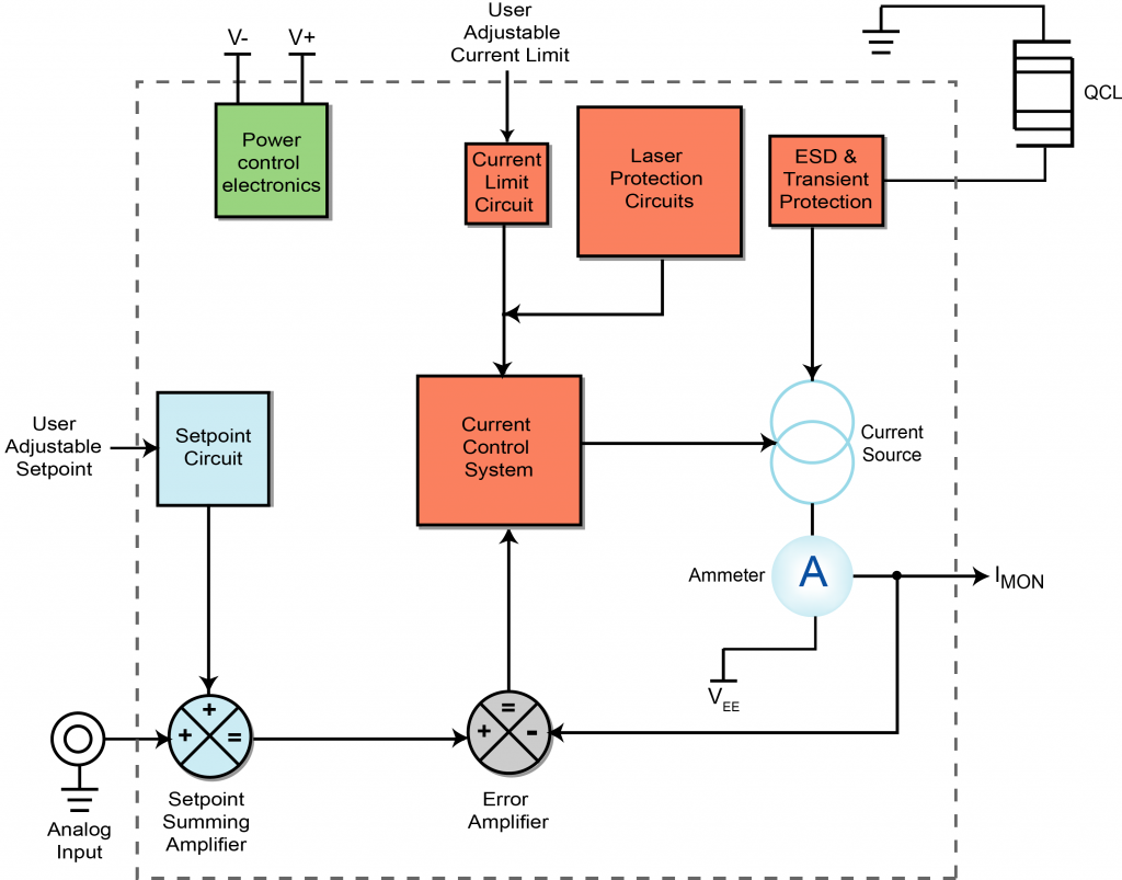
QCL: The QCL is a quantum cascade laser. The stepped icon indicates the cascaded nature of the output light. QCLs are used in remote sensing, IR imaging, and terahertz generation. |
 |
Current Source: Current flows through the quantum cascade laser as regulated by the current source. |
 |
Ammeter: Current through the QCL is measured and converted to a voltage signal called IMON. The IMON signal is fed back to the Error Amplifier |
 |
Summing Amplifier: Sums the onboard setpoint trimpot with the external analog modulation signal. |
 |
Error Amplifier: Generates a signal that is the difference between the actual laser current and setpoint. |
 |
Current Control: The current controller produces a signal to control the adjustable current source. The output signal from this stage is determined by the error amplifier. |
 |
Analog Input: An analog signal (e.g. a sine wave, triangle wave scan, or square wave) can be input to the QCL. This voltage signal is related to the actual current or power output by a transfer function. |
 |
Onboard Setpoint Circuit: Since setpoint is application specific, it must be adjustable by the user. |
 |
Limit Circuit: This section of the QCL driver is key to protect the laser diode. The user sets the limit current based on the operating parameters of the QC laser (typically well below damage threshold). |
 |
Laser Protection Circuits: The laser and driver are protected by internal circuitry so that neither is damaged in the case of power supply transients, over- or under-voltage events, or reversed power supply polarity. |
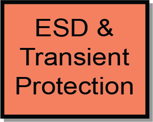 |
ESD and Transient Protection: While semiconductor lasers are far more robust and reliable than they were several years ago, they are still susceptible to damage by transients. Carefully designed transient safety protection circuits should be considered a necessity in any laser driver. |
 |
V+ and V-: The user provides power to the QCL driver. The driver has built-in power conditioning circuits to suppress power supply transients, and is linked to the Laser Protection Circuits. |
 |
VEE: Negative Load Supply |
Critical QCL Driver Features:
Because of the particular operating characteristics of QCLs, choosing the right driver is key to successfully implementing a QCL-based system.
The QCL center wavelength is current density dependent: current ripple and broad-spectrum noise manifest as a broadened output spectrum, so high stability and low noise are the two most important characteristics for a QCL driver. With a line width of 0.001cm-1 or less, and an output sensitivity of 0.01 cm-1 / mA, wavelength jitter due to driver noise can reduce overall system sensitivity by orders of magnitude.
Another critical characteristic that sets QCLs apart from single-junction diode lasers is the high compliance voltage, which can range from 5 V to 14 V depending on the device wavelength and manufacturer. This property alone eliminates most commonly available laser diode drivers for use with QCLs.
Eliminating current noise from the QCL driver is critical to take advantage of the lasing properties unique to single-mode quantum cascade lasers, and the driver circuitry must be designed with noise performance in mind from the beginning. Electronics shielding, cabling, and laser fixturing also play a critical role in noise reduction and must be designed carefully to maintain low electrical noise. Careless execution of fixturing and inadvertent ground loops can negate the effects of careful device design.
A driver with a well thought-out feature set is required in order to use the QCL for mid-IR gas sensing applications. For some sensing applications, quasi-CW current modulation is used to scan the output wavelength. A DC bias current is therefore necessary, and the modulation input must have a high enough bandwidth to take advantage of the current-dependent wavelength tuning capability of the QCL.
A critical function of the laser control system is temperature stability, which comes in two categories: temperature control of the laser itself, and the temperature stability of the QCL driver. Drivers with negligible temperature coefficient provide stable and uniform performance, thereby eliminating a major design concern and allowing the full capabilities of the QCL to be used across a wide range of application environments.
QCL output wavelength is sensitive to temperature variation, and improper temperature control will lead to suboptimal total system performance at best, and laser destruction in the worst case. DFB QCLs are tunable by about 0.1 cm-1 / K (see 1), so temperature stability in the range of ±0.001ºC is required for optimal wavelength stability. Sweeping the device temperature linearly through ambient takes full advantage of the laser wavelength tuning ability.
Essential laser control safety features should not be overlooked: brown-out protection and output current limits protect the QCL during operation; current soft-start and overvoltage circuitry protects the device from potentially harmful transients. The driver should also contain self-protection features: reverse voltage protection, and the ability to safely shut down the current source if ambient conditions cause the driver to overheat.
Critical Safety Circuits
Current Limit Circuit: The current limit is application specific, so it must be user-adjustable. The purpose of the current limit circuit is to protect the laser from over-current transients and accidental user inputs that might over-drive and destroy the laser.
Laser Protection Circuits: The laser protection circuits prevent adverse transient events from damaging the laser.
ESD Protection: ESD protection circuitry is crucial to protect the QCL from damaging ESD transients. Drivers without integrated ESD protection circuitry should be avoided.
Integrating the driver with the temperature controller provides a foolproof means for switching off the current source if the device temperature begins to run away, and should be considered a necessary safety feature of the QCL drive system.
QCL Driver Product Line
Wavelength’s family of Low Noise Quantum Cascade Laser Drivers is designed to be used on the test bench and then integrated into a production laser system. Rapid prototyping, ease of integration, built-in safety features, and reliable performance allow you to focus on the aspects of system design that are most challenging; you can leave the laser driver responsibilities to Wavelength Electronics.
The QCL Series is available in four different drive current models:
(1) Zeller, et. al., DFB Lasers Between 760 nm and 16 µm for Sensing Applications, (Sensors 2010, 10, ISSN 1424-8220)
(2) Evans82 at en.wikipedia
