What is a thermistor?
A thermistor is a resistance thermometer, or a resistor whose resistance is dependent on temperature. The term is a combination of “thermal” and “resistor”. It is made of metallic oxides, pressed into a bead, disk, or cylindrical shape and then encapsulated with an impermeable material such as epoxy or glass.
There are two types of thermistors: Negative Temperature Coefficient (NTC) and Positive Temperature Coefficient (PTC). With an NTC thermistor, when the temperature increases, resistance decreases. Conversely, when temperature decreases, resistance increases. This type of thermistor is used the most.
A PTC thermistor works a little differently. When temperature increases, the resistance increases, and when temperature decreases, resistance decreases. This type of thermistor is generally used as a fuse.
Typically, a thermistor achieves high precision within a limited temperature range of about 50ºC around the target temperature. This range is dependent on the base resistance.
The thermistor symbols are:
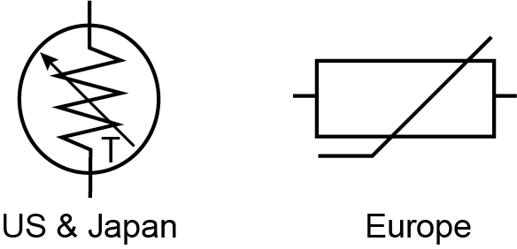
Figure 1: Thermistor Symbol — US and Japan
The arrow by the T signifies that the resistance is variable based on temperature. The direction of the arrow or bar is not significant.
Thermistors are easy to use, inexpensive, sturdy, and respond predictably to changes in temperature. While they do not work well with excessively hot or cold temperatures, they are the sensor of choice for applications that measure temperature at a desired base point. They are ideal when very precise temperatures are required.
Some of the most common uses of thermistors are in digital thermometers, in cars to measure oil and coolant temperatures, and in household appliances such as ovens and refrigerators, but they are also found in almost any application that requires heating or cooling protection circuits for safe operation. For more sophisticated applications, such as laser stabilization detectors, optical blocks, and charge coupled devices, the thermistor is built in. For example, a 10 kΩ thermistor is the standard that is built into laser packages.
How does the thermistor “read” temperature?
A thermistor does not actually “read” anything, instead the resistance of a thermistor changes with temperature. How much the resistance changes depends on the type of material used in the thermistor.
Unlike other sensors, thermistors are nonlinear, meaning the points on a graph representing the relationship between resistance and temperature will not form a straight line. The location of the line and how much it changes is determined by the construction of the thermistor. A typical thermistor graph looks like this:

Figure 2: Resistance vs. Temperature
How the change in resistance is converted into measurable data will be covered in detail below.
What is the difference between a thermistor and other sensors?
In addition to thermistors, several other types of temperature sensors are used. The most common are Resistance Temperature Detectors (RTD) and integrated circuits (IC), such as the LM335 and AD590 types. Which sensor works best for a particular use is based on many factors. The table below gives a brief comparison of the benefits and drawbacks of each.
PARAMETER
THERMISTOR
RTD
LM335
AD592
Temp Range
Within ˜50°C of a given center temperature
−260°C to +850°C
−40°C to +100°C
−20°C to +105°C
Relative Cost
Very inexpensive
Most expensive
Moderately expensive
Moderately expensive
Time Constant
6 to 14 seconds
1 to 7 seconds
1 to 3 seconds
2 to 60 seconds
Stability
Very stable, 0.0009°C
˜0.05°C
˜0.01°C
˜0.01°C
Sensitivity
High
Low
Low
Low
Advantages
- Durable
- Long lasting
- Highly sensitive
- Small size
- Lowest cost
- Best for measuring single point temperature
- Best response time
- Linear output
- Widest operating temperature range
- Best for measuring a range of temperatures
- Moderately expensive
- Linear output
- Moderately expensive
- Linear output
Disadvantages
- Nonlinear output
- Limited temperature range
- Slow response time
- Expensive
- Low sensitivity
- Limited temperature range
- Low sensitivity
- Large size
- Slowest response time
- Limited temperature range
- Low sensitivity
- Large size
Temperature Range: The approximate overall range of temperatures in which a sensor type can be used. Within a given temperature range, some sensors work better than others.
Relative Cost: Relative cost as these sensors are compared to one another. For example, thermistors are inexpensive in relation to RTDs, partly because the material of choice for RTDs is platinum.
Time Constant: Approximate time required to change from one temperature value to another. This is the time, in seconds, that a thermistor takes to reach 63.2% of the temperature difference from the initial reading to the final one.
Stability: The ability of a controller to maintain a constant temperature based on the sensor’s temperature feedback.
Sensitivity: The degree of response to a change in temperature.
Which thermistor shapes are available?
Thermistors come in a variety of shapes-disk, chip, bead, or rod, and can be surface mounted or embedded in a system. They can be encapsulated in epoxy resin, glass, baked-on phenolic, or painted. The best shape often depends on what material is being monitored, such as a solid, liquid, or gas.
For example, a bead thermistor is ideal for embedding into a device, while a rod, disk, or cylindrical head are best for optical surfaces. A thermistor chip is normally mounted on a printed circuit board (PCB). There are many, many different shapes of thermistors and some examples are:

Figure 3: Thermistor Types
Choose a shape that allows maximum surface contact with the device whose temperature is being monitored. Regardless of the type of thermistor, the connection to the monitored device must be made using a highly thermally conductive paste or epoxy glue. It is usually important that this paste or glue is not electrically conductive.
How does a thermistor work in a controlled system?
The main use of a thermistor is to measure the temperature of a device. In a temperature controlled system, the thermistor is a small but important piece of a larger system. A temperature controller monitors the temperature of the thermistor. It then tells a heater or cooler when to turn on or off to maintain the temperature of the sensor.
In the diagram below, illustrating an example system, there are three main components used to regulate the temperature of a device: the temperature sensor, the temperature controller, and the Peltier device (labeled here as a TEC, or thermoelectric cooler). The sensor head is attached to the cooling plate that needs to maintain a specific temperature to cool the device, and the wires are attached to the temperature controller. The temperature controller is also electronically connected to the Peltier device, which heats and cools the target device. The heatsink is attached to the Peltier device to help with heat dissipation.

Figure 4: Thermistor Controlled System
The job of the temperature sensor is to send the temperature feedback to the temperature controller. The sensor has a small amount of current running through it, called bias current, which is sent by the temperature controller. The controller can’t read resistance, so it must convert resistance changes to voltage changes by using a current source to apply a bias current across the thermistor to produce a control voltage.
The temperature controller is the brains of this operation. It takes the sensor information, compares it to what the unit to be cooled needs (called the setpoint), and adjusts the current through the Peltier device to change the temperature to match the setpoint.
The location of the thermistor in the system affects both the stability and the accuracy of the control system. For best stability, the thermistor needs to be placed as close to the thermoelectric or resistive heater as possible. For best accuracy, the thermistor needs to be located close to the device requiring temperature control. Ideally, the thermistor is embedded in the device, but it can also be attached using thermally conductive paste or glue. Even if a device is embedded, air gaps should be eliminated using thermal paste or glue.
The figure below shows two thermistors, one attached directly to the device and one remote, or distant from the device. If the sensor is too far away from the device, thermal lag time significantly reduces the accuracy of the temperature measurement, while placing the thermistor too far from the Peltier device reduces the stability.

Figure 5: Thermistor Placement
In the following figure, the graph illustrates the difference in temperature readings taken by both thermistors. The thermistor attached to the device reacted quickly to the change in thermal load and recorded accurate temperatures. The remote thermistor also reacted but not quite as quickly. More importantly, the readings are off by a little more than half a degree. This difference can be very significant when accurate temperatures are required.

Figure 6: Thermistor Location Response Graph
Once the placement of the sensor has been chosen, then the rest of the system needs to be configured. This includes determining the base thermistor resistance, the bias current for the sensor, and the setpoint temperature of the load on the temperature controller.
Which Thermistor resistance and bias current should be used?
Thermistors are categorized by the amount of resistance measured at ambient room temperature, which is considered 25°C. The device whose temperature needs to be maintained has certain technical specifications for optimum use, as determined by the manufacturer. These must be identified before selecting a sensor. Therefore, it is important to know the following:
What are the maximum and minimum temperatures for the device?
Thermistors are ideal when measuring a single point temperature that is within 50°C of ambient. If the temperatures are excessively high or low, a thermistor will not work. While there are exceptions, most thermistors work best in the range between -55°C and +114°C.
Since thermistors are nonlinear, meaning the temperature to resistance values plot on a graph as a curve rather than a straight line, very high or very low temperatures do not get recorded correctly. For example, very small changes in very high temperatures will record negligible resistance changes, which won’t translate into accurate voltage changes.
What is the optimum thermistor range?
Depending on the bias current from the controller, each thermistor has an optimum useful range, meaning the temperature range where small changes in temperature are accurately recorded.
The table below shows the most effective temperature ranges for Wavelength thermistors at the two most common bias currents.

Figure 7: Thermistor Selection Chart
It is best to choose a thermistor where the setpoint temperature is in the middle of the range. The sensitivity of the thermistor is dependent on the temperature. For example, a thermistor may be more sensitive at cooler temperatures than at warmer temperatures, as is the case with Wavelength’s TCS10K5 10 kΩ thermistor. With the TCS10K5, the sensitivity is 162 mV per degree Celsius between 0°C and 1°C, and it is 43 mV / °C between 25°C and 26°C, and 14 mV °C between 49°C and 50°C.
What are the upper and lower voltage limits of the sensor input of the temperature controller?
The voltage limits of the sensor feedback to a temperature controller are specified by the manufacturer. The ideal is to select a thermistor and bias current combination that produces a voltage inside the range allowed by the temperature controller.
Voltage is related to resistance by Ohm’s Law. This equation is used to determine what bias current is needed. Ohm’s Law states that the current through a conductor between two points is directly proportional to the potential difference across the two points and, for this bias current, is written as:
V = IBIAS x R
Where:
V is voltage, in Volts (V)
IBIAS is the current, in Amperes or Amps (A)
IBIAS means the current is fixed
R is resistance, in Ohms (Ω)
The controller produces a bias current to convert the thermistor resistance to a measurable voltage. The controller will only accept a certain range of voltage. For example, if a controller range is 0 to 5 V, the thermistor voltage needs to be no lower than 0.25 V so that low end electrical noise does not interfere with the reading, and not higher than 5 V in order to be read.
Assume the use of the above controller and a 100 kΩ thermistor, such as Wavelength’s TCS651, and the temperature the device needs to maintain is 20°C. According to the TCS651 datasheet, the resistance is 126700 Ω at 20°C. To determine if the thermistor can work with the controller, we need to know the usable range of bias currents. Using Ohm’s Law to solve for IBIAS, we know the following:
V / R = IBIAS
0.25 / 126700 = 2 µA is the lowest end of the range
5.0 / 126700 = 39.5 µA is the highest end
Yes, this thermistor will work, if the temperature controller bias current can be set between 2 µA and 39.5 µA.
When selecting a thermistor and bias current, it is best to choose one where the voltage developed is in the middle of the range. The controller feedback input needs to be in voltage, which is derived from the thermistor resistance.
Since people relate to temperature most easily, the resistance often needs to be changed to temperature. The most accurate model used to convert thermistor resistance to temperature is called the Steinhart-Hart equation.
What is the Steinhart-Hart Equation?
The Steinhart-Hart equation is a model that was developed at a time when computers were not ubiquitous and most mathematical calculations were done using slide rules and other mathematical aids, such as transcendental function tables. The equation was developed as a simple method for modeling thermistor temperatures easily and more precisely.
The Steinhart-Hart equation is:
1/T = A + B(lnR) + C(lnR)2 + D(lnR)3 + E(lnR)4…
Where:
T is temperature, in Kelvins (K, Kelvin = Celsius + 273.15)
R is resistance at T, in Ohms (Ω)
A, B, C, D, and E are the Steinhart-Hart coefficients that vary depending on the type of thermistor used and the range of temperature being detected.
ln is Natural Log, or Log to the Napierian base 2.71828
The terms can go on infinitely but, because the error is so small, the equation is truncated after the cubed term and the squared term is eliminated, so the standard Steinhart-Hart equation used is this:
1/T = A + B(lnR) + C(lnR)3
One of the pleasures of computer programs is that equations that would have taken days, if not weeks, to solve are done in moments. Type “Steinhart-Hart equation calculator” in any search engine and pages of links to online calculators are returned.
How is the Steinhart-Hart Equation used?
This equation calculates with greater precision the actual resistance of a thermistor as a function of temperature. The more narrow the temperature range, the more accurate the resistance calculation will be. Most thermistor manufacturers provide the A, B, and C coefficients for a typical temperature range.
Who are Steinhart and Hart?
John S. Steinhart and Stanley R. Hart first developed and published the Steinhart-Hart equation in a paper called “Calibration curves for thermistors” in 1968, when they were researchers at Carnegie Institution of Washington. Steinhart went on to become Professor of Geology and Geophysics, and Marine Studies at the University of Wisconsin-Madison and Stanley R. Hart became a Senior Scientist at Woods Hole Oceanographic Institution.
Conclusion
Thermistors are temperature-dependent resistors, changing resistance with changes in temperature. They are very sensitive and react to very small changes in temperature. They are best used when a specific temperature needs to be maintained, and when monitoring temperatures within 50°C of ambient.
Thermistors, as part of a temperature control system, are the best way to measure and control heating and cooling of a Peltier device. Their ability to adjust in minute increments allows the greatest overall system stability. Thermistors can be embedded in or surface-mounted on the device needing temperature monitoring. Depending on type, they can measure liquids, gases, or solids.
Wavelength supplies a variety of bead and cylindrical head thermistors. For a listing of the current selection, click here.
