What is a precision temperature controller?
The purpose of a temperature control system is to maintain a device at a constant temperature. Two types of actuators are commonly used to precisely control the temperature of optics, lasers, biological samples, or other temperature sensitive devices. One is a thermoelectric, or Peltier device. The other is a resistive heater. A precision temperature controller uses a current or voltage source to drive power through these actuators based on feedback from a temperature sensor. The temperature sensors are typically thermistors, RTDs, or linear devices such as the LM335 or AD590. With these types of sensors, stabilities of 0.01°C to 0.001°C are commonly achievable. Less precise sensors – thermocouples – can also be used for stabilities of about 1°C. The design of the system dictates the stability. If the sensor, actuator, and device being stabilized are poorly connected, the best controller in the world can’t help. The following block diagram shows a very basic temperature control circuit. Each symbol is defined in the table below. Each section is described in detail below. Temperature Controllers vary widely in feature set and performance. This block diagram is a representative sample, meant to familiarize the users with terminology and basic elements, not an exhaustive evaluation of what is available on the market.
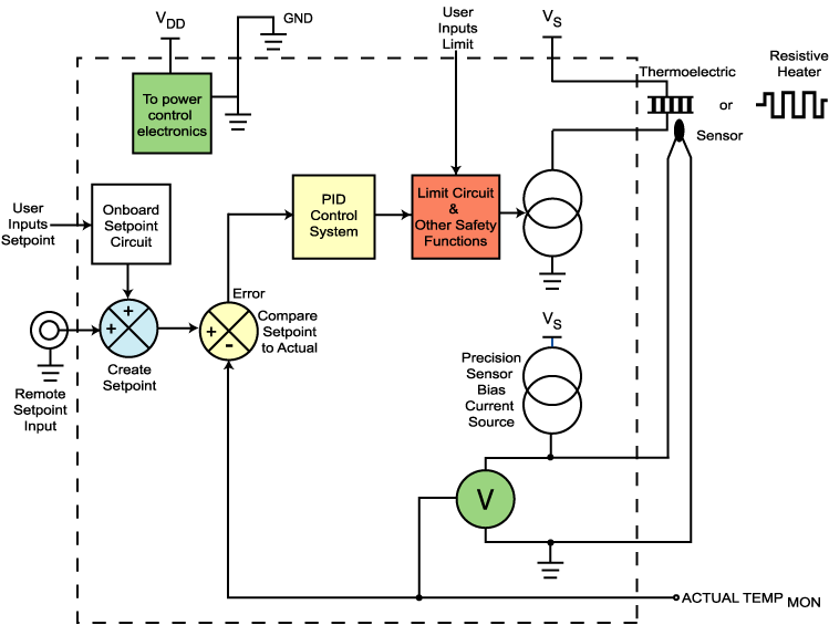
Figure 1: Temperature Controller within the dashed lines
| Symbol | Name & Brief Description |
|---|---|
|
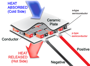
Thermoelectric: Based on the Peltier effect, current flow in one direction causes heat to be transferred from Surface A to Surface B. Current flow in the opposite direction causes heat to be transferred from Surface B to Surface A. It is often called a heat pump, Peltier cooler, or thermoelectric cooler.
|
|
| Resistive Heater: Like a toaster element, current flow through a resistive heater is converted to heat. | |
 |
Sensor: To provide feedback for the controller, actual temperature must be measured and converted to a voltage input. A common sensor is a Thermistor. This is a resistor that changes resistance with temperature. Most thermistors are Negative Temperature Coefficient (NTC). This means resistance decreases as temperature increases. Resistance Temperature Detectors (RTDs) are Positive Temperature Coefficient (PTC) devices. Resistance increases as temperature increases. Their response is more linear than thermistors, but they are not as sensitive, leading to lower stability. In either case, a precision current source from the temperature controller drives current through the sensor, providing a voltage feedback for the control system. |
 |
Adjustable & Bi-directional Current Source: Current flows through the thermoelectric or resistive heater as regulated by the current source. |
 |
Precision Sensor Bias Current Source: Current flows through the sensor to develop a voltage proportional to the resistance of the sensor and therefore sensor temperature. |
 |
Voltmeter: Measures voltage across the sensor. The ACT TMON voltage represents the resistance of the sensor which translates into temperature. |
 |
Summing Amplifier: These are used to measure the difference between setpoint and actual temperature, or to sum the onboard setpoint trimpot with a remote analog setpoint signal. |
 |
Remote Setpoint Input: An analog signal (usually a triangle wave scan or DC voltage) can be input to the temperature controller. This voltage signal is related to the actual sensor temperature by a transfer function. |
 |
Onboard Setpoint Circuit: Since setpoint is application specific, it must be adjustable by the user. |
 |
Control System: Here the error between the setpoint temperature and the actual temperature is acted on to drive the appropriate amount of current to the temperature actuator (thermoelectric or resistive heater). |
 |
Limit Circuit: This section of the temperature controller protects the thermoelectric or resistive heater and the device under temperature control. Thermoelectrics are approximately 10% efficient. The electrical power delivered to the thermoelectric is converted to heat that must be removed from the load. The “hot” side of the thermoelectric is mounted to a heatsink with enough capacity to remove the heat from the device under temperature control AND the excess lost in the thermoelectric. If the heatsink is inadequate, the sensor reports an increase in temperature to the controller which then drives more current through the thermoelectic, adding more heat to the inadequate heatsink. This cycle is called thermal runaway. The user sets the limit current based on the operating parameters of the thermoelectric and the maximum capacity of the heatsink. |
|
Safety Functions: Usually a thermoelectric is used in conjunction with a device that is sensitive to temperature. If the thermoelectric fails, or the system reaches a temperature too high for the device, various safety signals can be tripped to shut off power to the device. |
Temperature Controller Current Source: One key section of a temperature controller is the Adjustable, Bi-directional Current Source. It can also be known as the Output Stage. This section responds to the Control System section by driving current to the temperature actuator (thermoelectric or resistive heater). The direction of the current is critical to thermoelectrics. In the block diagram, the thermoelectric is tied between the two pins on the controller. For the resistive heater, special wiring may be required to restrict current flow through the resistive heater to only one direction.
Control System: User inputs include the limit setpoint (in terms of maximum current allowed to the thermoelectric or resistive heater) and the operating setpoint. Additionally, if a remote setpoint is required, a Remote Setpoint Input is usually available.
- Setpoint: This is an analog voltage into the system. It can be created by a combination of onboard trimpot adjustment and the Remote Setpoint Input. In some cases, these inputs sum. Some act independently.
- Precision Sensor Bias Current Source: This current source drives the temperature sensor at a known level, making the actual sensor voltage stable and accurate. The voltage across the sensor is given by Ohms Law: V = I * R where V is the voltage, I is the current, and R is the resistance of the sensor. The voltage is bounded by a maximum and minimum (given by the temperature controller datasheet). The lowest possible current should be used to minimize the effects of self-heating. A thermistor will heat up at higher current levels and falsely report a higher temperature.
- Error Generation: To know how the system is functioning, the Actual Temperature is compared to the Setpoint Temperature. These two voltages are subtracted and the result is called the “Error.” The output of the Adjustable Current Source will vary to keep the temperature feedback signal the same.
- PID Control System: This converts the error signal into a control signal to the Adjustable Current Source. A more thorough discussion of PID control can be found in Technical Note TN-TC01
- Limit Circuit: One way to damage a thermoelectric is to drive too much current through it. Each actuator datasheet will specify a maximum operating current. Exceeding this current will damage the device. To avoid this, a limit circuit is included in the temperature controller. The user determines the maximum setting and the output current is kept from exceeding that level. Most limit circuits cap the current at the max level and keep operating.
- Safety Features: Thermoelectrics and resistive heaters are sensitive to overpowering, but they are robust with respect to fast changes in current or voltage. Safety features may include a “thermal runaway” condition indicator. Temperature limits – both high and low – can also be available to trigger indicators or shut down output current.
Power: Power must be provided to the control electronics and current source. This can take the form of a DC power supply (some drivers use single supply inputs, others use dual supplies), or an AC input connector and cable. In some cases, where higher voltage is required to the thermoelectric or resistive heater, separate DC power supply inputs may be available to power the control electronics from a low +5 V supply and the thermoelectric from a higher voltage supply.
What is the difference between an instrument, a module, and a component?
Usually price, feature set, and size. An instrument typically has a front panel with knobs and button adjustments and some form of display to track the sensor. These can all be automated with computer control via USB, RS-232, RS-485, or GPIB. An instrument is usually powered by AC, not a DC power supply. By our definition, a module doesn’t include the display or power supply, and has the minimum required adjustments. To monitor status, a volt meter measures voltage and the module datasheet provides a transfer function to convert the voltage to actual sensor resistance. The sensor data sheet converts sensor resistance to temperature. Some devices allocate memory for calibrating the sensor response. A component is further stripped down, with no moving parts. External resistors or capacitors set operating parameters. Safety features are common to all three forms. Usually, modules can sit on a benchtop or be integrated into a system using cables. Components mount directly to a printed circuit board (PCB) with plate-through or surface mount (SMT) pins. Two rows of pins are referred to as DIP packaging (dual-in-line), while a single row of pins is called SIP packaging (single-in-line).
A variety of off-the-shelf controllers are available in both instrument and OEM packages. Some vendors are blurring the boundaries, for example, offering USB control of components as mini-instruments.
Packaging of components and modules includes proper heatsinking of the circuit elements (or guidance on how the device should be heatsunk) and usually includes the appropriate cabling to the thermoelectric, sensor, and power supply. Instruments include a power cord and user access inside the case is not necessary.
Typical terminology:
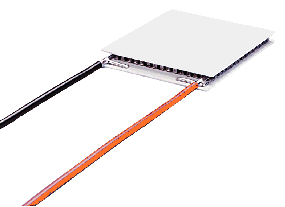
Thermoelectric: This is a device characterized by two ceramic plates that bound metal junctions made of two dissimilar metals. If current flows through the junction of dissimilar metals, heat is generated at one side while it is absorbed at the other side. By flowing current through a thermoelectric, heat is transferred from one ceramic plate to the other. The direction of current dictates which plate becomes “hot” and which becomes “cold” relative to each other. Reversing the current immediately reverses the effect. A temperature controller works by optimally controlling the magnitude and direction of current through the junction to maintain a device attached to the “cold” side at a fixed temperature. Thermoelectrics can be stacked on each other to create wider temperature differentials. These are called multi-stage or cascaded thermoelectrics. A thermoelectric can also convert a temperature differential into electricity. This is called the Seebeck Effect. A thermoelectric is also known as a thermoelectric cooler, a peltier device, or a solid state heat pump.
Q MAX: A specification of the thermoelectric. This is the maximum power that it can absorb into the cold plate.
Delta T MAX: A specification of the thermoelectric. This is the maximum temperature differential that can be created by the thermoelectric between its plates. It is specified at IMAX and VMAX and for a specific temperature of the “hot” plate.
I MAX and V MAX: Maximum Current and Voltage specifications of the thermoelectric, respectively. Do not exceed these operating conditions.
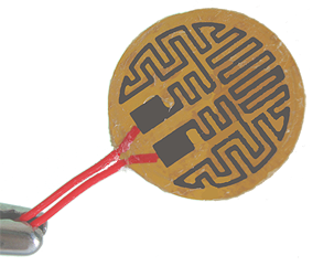
Resistive Heater: Usually these heaters are flexible with a resistive element sandwiched between two insulators. The materials of the resistive element and insulators vary greatly with application. Some require AC power, not DC current that a typical temperature controller produces. With a resistive heater, current flow either direction generates heat; therefore, there is no active cooling function. Cooling is accomplished by dropping current flow to zero and allowing the heat to dissipate into the ambient surroundings. Stabilities are typically not as good as those achieved with a thermoelectric, unless the operating temperature is significantly higher than ambient.
Ambient Temperature: This is usually the temperature of air / environmental conditions around the load.
Disable: When output current is disabled, all safety mechanisms are usually set to an initial power on state and only a residual leakage current is delivered to the thermoelectric.
DVM: Digital Volt Meter, a meter that monitors voltage.
Ammeter: A meter that monitors current.
ESD: Electro-static Discharge. The “zap” one feels crossing a carpet & touching a metal door knob is the most common example of ESD. Laser diodes are sensitive to ESD. A “zap” that a human doesn’t feel is still enough to damage a laser diode. Proper ESD precautions should be followed whenever handling a laser diode or other ESD sensitive electronic equipment.
Internal Power Dissipation: With a linear current source, some of the power delivered by the power supply goes to the thermoelectric or resistive heater, and some is used in the temperature controller. The Maximum Internal Power Dissipation of a controller is the limit past which thermal damage to internal electronic components is possible. Designing a temperature control system includes choosing the power supply voltage. If a 28 V supply is chosen to drive a thermoelectric whose voltage is 6 V, 22 V will be dropped across the temperature controller output stage (or current source). If the driver is running at 1 Amp, the internally dissipated power will be V * I or 22 * 1 = 22 Watts. If the internal power dissipation specification is 9 Watts, the Current Source components will overheat and suffer permanent damage. Wavelength provides online Safe Operating Area Calculators for all components and modules to simplify this design choice.
Compliance Voltage: The Current Source has an associated voltage drop across it. Compliance Voltage is the power supply voltage minus this internal voltage drop. It is the maximum voltage that can be delivered to the thermoelectric or resistive heater. It is typically specified at full current.
Current Limit: In the thermoelectric or resistive heater datasheet, Maximum Current will be specified at an ambient temperature. Above this current, the device can be damaged. At higher temperatures, this maximum value will reduce. The Current Limit is the maximum current the Current Source will deliver. The Current Limit can be set below the thermoelectric maximum current, and used as a tool to minimize the Internal Power Dissipation of the temperature controller. With a higher current limit, the thermoelectric will transfer more heat faster, so time to temperature can be reduced (if the control system is optimized to avoid overshoot and ringing).
Load: For a temperature controller, the load consists of the temperature actuator (thermoelectric or resistive heater) and the temperature sensor.
ACTUAL TEMP MON: This is an analog voltage proportional to the resistance of the temperature sensor. Transfer functions to resistance are provided in individual controller datasheets. Converting resistance to temperature uses transfer functions from the sensor datasheet. This can also be called ACT T Monitor or Temperature Monitor.
VSET: This is a common term used to refer to the Remote Setpoint Input signal. V indicates a voltage signal while SET indicates its purpose: control system setpoint. It can also be called MOD, MOD IN or ANALOG IN.
What are typical specifications and how do I interpret them for my application?
At present, each vendor conducts their own testing and there is no standard for measurement. Once you identify a solution for your application, it is critical to test the product in your application to verify operation. Here are some of the definitions Wavelength uses and how to interpret the specifications in your design.
Input Impedance: This is specified for analog voltage inputs such as VSET or MOD IN. It is used to calculate how much current an external signal generator must source. For example, if VSET is being driven by a D/A converter, with a maximum voltage of 5 V and an input impedance of 20 kΩ, the D/A converter must source at least 5 V / 20000 Ω or 0.25 mA.
Stability: For a temperature controller, how stable a system can be held is usually a critical specification. Wavelength tests using thermistors because they offer the highest resistance change per degree C. The test load is also well designed, with the sensor close to the device being controlled and the thermoelectric, the heatsink properly sized, and components connected with high quality thermal grease to minimize thermal resistance between them. Stability is given in Kelvin or Celsius. Typical stabilities can be as low as 0.001°C. A more detailed Technical Note TN-TC02 describing the testing is available online.
Operating Temperature Range: Electronics are designed to operate properly across a designated temperature range. Outside of the minimum and maximum temperatures, damage can occur or behavior can change. The operating range that Wavelength specifies is coupled with the Maximum Internal Power Dissipation specification. Above a certain ambient temperature (usually 35°C or 50°C) maximum internal power dissipation derates to zero at the maximum operating temperature.
Operating Voltage Range: In some temperature controllers, two supply voltages can be used – one to power the control electronics (VDD) and one to provide higher compliance voltage to the thermoelectric or resistive heater (VS). Typically, the control electronics operate on lower voltages: 3.3 to 5.5 V. Exceeding this voltage can damage elements in the Control or Power sections. The Current Source (or Output Stage) is designed for higher voltages (such as 30 V with the PTC family of temperature controllers). This specification needs to be considered in conjunction with the drive current and power delivered to the load to make sure the design does not exceed the Maximum Internal Power Dissipation specification. For example, the PTC5K-CH is specified to operate up to 5 Amps and it can accept a 30 V input. It’s maximum internal power dissipation is 60 Watts. If 28 V is used to power a thermoelectric which drops 4 V, 24 V will drop across the PTC5K-CH. At 24 V, the maximum current within the safe operating range is less than 60 / 24 or 2.5 Amps. Driving more than that current will overheat the Output Stage components and irreversibly damage the controller. The maximum current and voltage specifications are tied, not independently achievable.
Monitor vs. Actual Accuracy: The ACT T MON signal is an analog voltage proportional to sensor resistance. The accuracy of the actual resistance relative to the measured values is specified in the individual driver datasheets. Wavelength uses calibrated, NIST traceable hardware to ensure this accuracy specification.
Separate Monitor & Power Grounds: One high power ground is designated to connect to the power supply on any temperature controller . Several low current grounds are located amongst the monitor signals to minimize offsets and inaccuracies. While high and low current grounds are tied internally, for best results, use a low current ground with any monitor.
Linear or switching power supplies for components and modules: Linear power supplies are relatively inefficient and large compared to switching power supplies. They are, however, low noise. If noise is critical to your system, you can try a switching power supply to see if the switching frequency affects performance anywhere in the system.
Thermal Runaway: If a thermoelectric is removing heat from a device (cooling it to below ambient temperature), that heat must be dissipated out of the system. The additional heat from inefficiencies in the thermoelectric must also be dissipated. If the heatsink design is adequate, enough heat is removed so that the device can be maintained below ambient temperatures. If however, the design is marginal, the heat stays in the load, and the sensor temperature rises instead of staying at the desired temperature. The control system reacts by driving more cooling current through the thermoelectric. This results in more heat being generated in the load and a continued rise in the sensor temperature. This is called “thermal runaway.” The temperature of the system is not controlled, but dictated by inadequate heat dissipation to ambient surroundings.
Wavelength designs temperature controllers and manufactures them at a facility in Bozeman, Montana, USA. For a listing of the current temperature controller selections, click here.
Useful sites:
External links are provided for reference purposes. Wavelength Electronics is not responsible for content of external sites.
