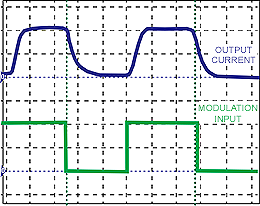
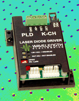
The setpoint input looks like a clean square wave. Why does my laser diode output current look different? This is one of the most common questions asked of our technical support engineers. The reason usually involves the frequency response of the output stage of the laser diode driver. To measure the bandwidth of a laser diode driver, Wavelength engineers deliver a sine wave (with positive DC bias) into the setpoint input of a laser diode driver. The sine wave peak-to-peak is 1 V. Using the laser diode driver transfer function, an equivalent output current is calculated. At low frequencies, the sine wave input drives according to the transfer function. At higher frequencies, the output sine wave peak-to-peak value decreases. The frequency where the output current is half the expected current is called the 3dB frequency and is noted as the bandwidth of the laser diode driver. This applies to sine waves. The response to a square wave or triangle wave is more complicated. The harmonics of the square wave frequency that exceed the 3dB bandwidth are attenuated, so the output current shape starts to resemble a sine wave. TN-LD03: PLD Series Laser Driver Modulation & Wiring Recommendations details other wave form distortions seen when positive bias is missing or cables are too long or untwisted.
Subscribe to our newsletter for tips, techniques & product updates.
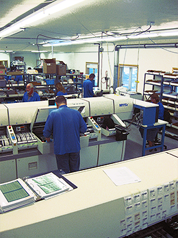
Last year, Wavelength Electronics was qualified to reliably place fine pitch BGAs to IPC Class 3 standards. To support this added capability as well as increasing sales of standard product, Wavelength has recently doubled manufacturing capacity. “Our dedication to product reliability and robustness requires that we work with state-of-the art equipment and keep staff well-trained,” says CEO Mary Johnson. “Our industry-low RMA rate is proof of our commitment to our OEM partners. We’ve invested in increasing our capacity to make sure we can meet growing demands while maintaining quality.”
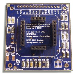
The WTCP5A5V PWM temperature controller can be quite complicated to evaluate. That’s why Wavelength offers the WTCPEVAL board and instructions on how to optimize the WTCP in your application. Once you have found it works efficiently in your system, only a few fixed value external components are required. Wavelength now offers a small OEM board, loaded with values you specify to get the WTCP integrated into a system quickly. Details can be found here.
For more information, contact your technical support engineer at techsupport@teamwavelength.com.
Hints for Using Multiple Thermoelectrics
If the size of your temperature controlled load is large, you may choose to use more than one thermoelectric (TE) to stabilize your system. There are several tricks to using more than one thermoelectric effectively.
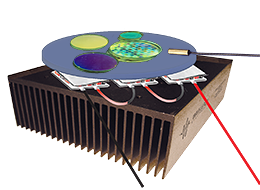
We recommend that you run the thermoelectrics electrically in series. If you operate them in series, they will each see the same control current. Even with the same current, the cooling capacity of each TE may differ, and one side of the load can become cooler than the other. If only one feedback sensor signal is used, the system usually stabilizes. Position of the sensor is critical. For the most accurate temperature, place the sensor right at the critical element whose temperature needs to be stabilized. For a more stable, average temperature, put the sensor closer to the TE and centralized in the load. Experiment with sensor location to optimize the control system. To run in series, add the voltages of the thermoelectrics to see what total voltage the controller must support.
If you run the thermoelectrics in parallel, they’ll each take a portion of the control current based on their effective impedance. The impedance of a TE is dynamic (it changes with current) so what typically happens is that one takes more current than the other and forces one section cooler than the other, further changing its impedance. By the time the change reaches the common sensor, the setpoint has been overshot. The current then is reduced or reversed so the net effect is that the temperature at the sensor oscillates.
We also do not recommend putting multiple sensors in series around the area to be cooled. Instead of feeding an average temperature back to the control loop, the sensors “report” changes to their individual locations and the net effect is to cause the load temperature to oscillate.
For ultimate control and stability, use one controller and sensor per thermoelectric.
We invite you to contribute topic suggestions, questions, and general feedback. Wavelength will incorporate as much reader input as possible.
Click to Submit


