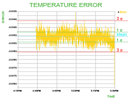
Stability is how close the actual load temperature stays to the setpoint temperature over time. We operate a temperature controller with a thermoelectric, laser diode, and thermistor. We monitor actual temperature of the sensor. Error is the difference between actual sensor and setpoint temperatures. Our typical (TYP) stability specification is three times the standard deviation of the error over the specified time period.
Our Technical Note TN-TC02: How is Temperature Stability Measured? explains how we test and measure stability in our temperature controllers.

Subscribe to our newsletter for tips, techniques & product updates.

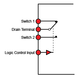
If your Wavelength Electronics controller uses a fixed resistor to set the output current limit(s), you can also use a digital signal to enable or disable the output current remotely. This FAQ details which switch we recommend and how to implement the circuitry.

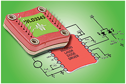
Many pages of the WTC temperature controller and WLD laser diode driver datasheets are devoted to the details of how to optimally choose the external component values specific to your application. The Design Calculator tools let you skip these pages and provide a wiring diagram specific to your system with values of external components already calculated. For example, on the WTC design calculator, you enter the desired setpoint temperature, whether you’re using a thermoelectric or resistive heater, the sensor type, and what bias current you’ll be using with that sensor. Click Update Circuit, and print your wiring diagram. Then, to make sure your power supply voltages will not be too high, Wavelength provides a Safe Operating Area (SOA) tool to calculate the WTC or WLD internal power dissipation during operation with your settings. To use the WTC SOA Calculator, choose the Wavelength controller you’re using (WTC3243 with heatsink and fan), enter the ambient system temperature, the limit current setting for your system, the thermoelectric load impedance (VMAX / IMAX), and the power supply voltage you intend to use. Click Find SOA Compliance to see whether your system will melt down or operate reliably. See AN-LDTC01: Principle of the Safe Operating Area for details.

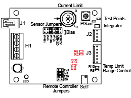
The setpoint voltage for the PTC family of precision temperature controllers needs to be the same voltage the sensor will produce at the desired operating temperature. For example, the resistance of a 10 kΩ thermistor (such as TCS-610) at 10°C will be 19900 ohms. If using a 100 µA bias current, the voltage across the thermistor will be 1.99 V. To control the system to 10°C, the setpoint voltage needs to match the 1.99 V. If the setpoint is provided by a DAC or other circuit and that signal is lost, the setpoint will drop to 0 V. For a 10 kΩ thermistor, this translates to a setpoint point greater than 50°C. The temperature controlled system could be damaged at a temperature of 50°C. Wavelength has designed a failsafe on the setpoint circuit to avoid inadvertant overheating of the system. If the setpoint voltage drops below 0.3 V, the failsafe circuit kicks in and forces the setpoint to 1 V (about 25°C for a 10 kΩ thermistor). To test this in action, we recommend that you set your heating and cooling current limits low, set the setpoint jumper to “internal trimpot”, and monitor the SET T MON signal with a DVM or oscilloscope. Turn the onboard setpoint trimpot down until it goes below the trip point. Watch the setpoint monitor change to 1 V. The trip point and the default failsafe voltages can be customized. See AN-TC07 for details.
We invite you to contribute topic suggestions, questions, and general feedback. Wavelength will incorporate as much reader input as possible.
Click to Submit

