Introduction
Modulating the output power of a laser diode can happen in two ways: by changing the signal input/driving current1,2 or by alternating the continuous wave output after the light is generated.2 In laser modulation, the current or voltage varies with time to modulate the output signal from the laser. Direct Modulation is when the current, before reaching the laser diode, is modified with the desired signal for the application. This uses a function generator to create the modulation signal and a laser diode driver to apply the signal to the drive current for the laser. External Modulation is when the modulation is imposed onto the laser signal after the light is generated.2 Modulation such as Electro-Optic Modulation (EOM), Acousto-Optic Modulation (AOM), and Electro-Absorption Modulation (EAM) can be used to manipulate the laser output with electric fields or sound waves. Both types of laser diode modulation are shown in Figure 1.
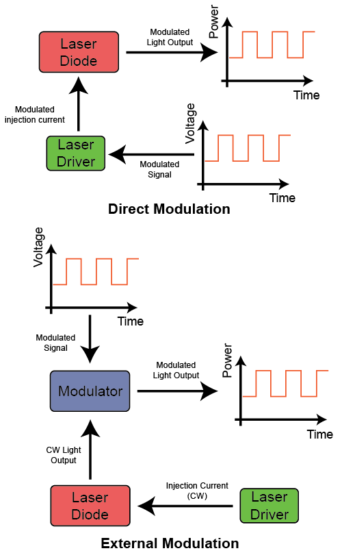
Figure 1. Direct modulation and external modulation schematics
Modulation can be useful for a variety of applications in the world of lasers. The capacity of transmitted data can be increased with high frequency sources and modulators for many communication applications.3 Laser modulation offers an alternative method for light detection and ranging (LIDAR) measurements with benefits of lower danger of eye damage and higher sensitivity than with continuous wave (CW) lasers. When ultra-high output powers are not needed from pulsed lasers, as in the case of spectroscopy, modulated lasers can provide fast data acquisition, reduce the system costs, and enable high resolution without damaging the sample. Other types of research or experiments involving sample imaging have similar benefits from laser diode modulation.
Laser modulation can be analog or digital (Figure 2), with different benefits. Analog Modulation is a continuous and smooth signal that is limited to a range of values. A power vs. time graph in the shape of a sine wave is a perfect example of analog modulation where the signal changes smoothly over time. Digital Modulation has a set of finite, discreet values. A square wave is a signal with two set values to switch between. This is often used to turn a laser on and off with the low point being below threshold. The laser operates like an LED below the threshold current with spontaneous emission, and the laser operates with stimulated emission above threshold. In direct modulation, using a digital signal through an analog input on the laser driver can cause distortion to the output power or signal of the laser.
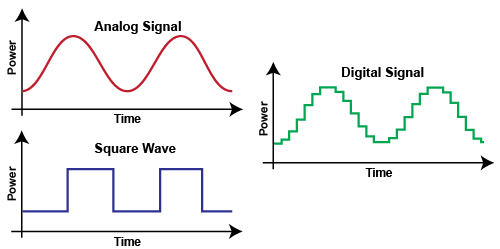
Figure 2. Analog and Digital Modulation Signals and Square Wave Signal
Direct Modulation
Direct Modulation is when the modulation signal is introduced before the laser emission. Input current effects electron (charge carrier) density and therefore optical output power non-linearly. Figure 3 shows how a current setpoint or current step (without any current bias) results in oscillations in both electron density and optical output power.
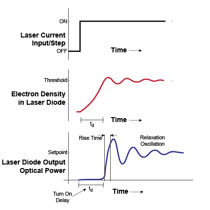
Figure 3. Effects of input current on laser diode optical output power with respect to time2
The initial overshoot in optical output power is followed by a few cycles of damped oscillation. Before stabilization, this is called the Relaxation Oscillation. There is an inverse relationship between carrier density and photon density in the semiconductor. As the photon density increases, the recombination rate of electrons and holes increases. This leads to a reduction in the carrier density as free electrons and holes recombine, reducing the optical gain and intensity. The reduced optical intensity allows the carrier density to build back up, and the cycle continues to oscillate until eventually reaching stability.3 Most laser diodes dampen the Relaxation Oscillation, but it can still be problematic for very sensitive measurements and equipment.
Also seen in Figure 3 are the Turn-on Delay and the Rise Time. When a laser is suddenly injected with current, the output power will be slightly delayed until the injection current surpasses the threshold for lasing. This directly correlates to the electron density. Of course the laser does not immediately produce the desired lasing output once current has reached the threshold. All lasers have some amount of rise time – the time for the optical output to rise from 10% to 90% of its set or maximum value. There is a similar effect when current is no longer injected to the laser and is turned off. Fall Time is the amount of time for the optical output to fall from 90% to 10% of its set or maximum value.
These three parameters (Turn-on Delay, Rise Time, and Fall Time) are critical design factors when modulating the laser. If the minimum current value in the modulation signal is below the laser threshold, lasing will not occur and there may be distortion with every signal step or rise in current. Distortion will alter the modulation output waveform of the laser creating differences in desired modulation and actual output. To eliminate the typical times of picoseconds and microseconds for delay and rise times, the minimum drive current should not fall below the threshold.4
Another parameter that can influence distortion is bandwidth. The 3dB modulation bandwidth is typically specified for a laser system. This is the frequency through the laser that attenuates the output by half. If the laser is modulated with a frequency approaching or greater than the bandwidth, the output signal will not match the input modulation signal and is distorted and significantly attenuated as seen in Figure 4.

Figure 4. The system response (blue, bottom) cannot adequately maintain the desired waveform output (yellow, top) if the frequency of the waveform is greater than the effective bandwidth of the system. Here the input frequency is less than 25 Hz above the specified maximum bandwidth.
Bandwidth is usually given for a sine wave frequency. Using a different waveform, such as a square wave, can create larger attenuation and distortion at the same frequency as when using a sinusoidal frequency. Application Note AN‑LDTC05: Bandwidth Basics has more information about modulation bandwidth and how it is measured.
External Modulation
Instead of modulating lasers by changing the injection current, External Modulation uses a device external to the laser to apply the modulation to the continuous wave (CW) laser output. There are three main electrical techniques of modulating the CW output of a laser: Electro-Optic Modulation (EOM), Electro-Absorption Modulation (EAM), and Acousto-Optic Modulation (AOM). Other external modulation techniques include mechanical methods: shutters, choppers, and spinning disks. This application note focuses on the three electrical modulation techniques.
ELECTRO-OPTIC MODULATION
The EOM method is based around the Pockels Effect, which is the change in refractive index of a material due to the application of an electric field.4 These modulators come in the form of nonlinear crystals for bulk devices, waveguides or waveplates, and special polymers. If a voltage is applied across a nonlinear crystal, an electric field is produced, thus changing the refractive index of the material. As light passes through the material, the phase of the light will be altered with respect to the voltage applied to the modulator. The phase shift is related to select parameters of the waveguide or crystal as well as the laser light given by Equation 1.
Equation 1. EOM Phase

where r is the electro-optic coefficient, n is the index of refraction, E is the electric field, L is the length of the optical waveguide, and λ is the wavelength. E = V/d when an electric field is produced by applying a voltage V across the waveguide of width d. Consequently, modulating the phase of the laser light is accomplished by varying the voltage V across the material.4
When a phase modulator is combined with a Mach-Zehnder interferometer or modulator (Figure 5), the intensity or amplitude of the laser output can be modulated. When the beam is split in the interferometer, a Pockels Cell (in one arm) changes the phase of that specific arm and portion of light. When the two arms combine outputs, they will either constructively or destructively interfere, changing the final intensity of the light.
The Pockels Effect can provide extremely high speeds with external modulation. Integrated-optic modulation uses a dielectric optical waveguide and the linear electro-optic effect to change the index of refraction of the waveguide. Bulk devices utilize a discrete piece of a nonlinear optical crystal. Integrated-optic EOM generally operates at lower voltages than bulk devices and allows for optical fiber coupling. Temperature control of the device may be needed for high powers and fast modulation.
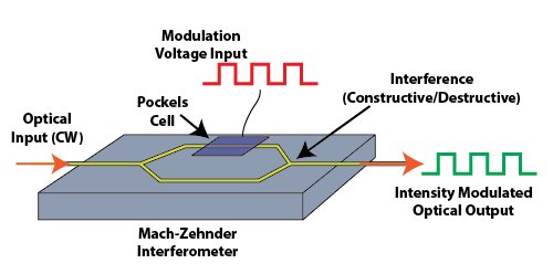
Figure 5. Electro-Optic Modulator combined with a Mach-Zehnder Interferometer
ELECTRO-ABSORPTION MODULATION
The EAM method (Figure 6) is based on the Fraz-Keldysh and Stark Effect, which is the change in light absorption of a waveguide due to the application of an electric field. Once again, this is accomplished with an applied voltage across the waveguide. The semiconductor is transparent to light without the electric field present. When voltage is applied the bandgap energy decreases. The material will absorb the light once the photon energy exceeds the bandgap energy, attenuating the light transmission. When the voltage is modulated, the absorption of the material and the output light intensity can be modulated.3,4 Because the energy is mostly converted into heat, thermal solutions are needed to ensure precise modulation without unwanted thermal effects. EAM can be useful in even lower voltage applications than EOM and optical fiber communications. It is also easy to integrate on to a distributed feedback laser chip for smaller size and simple operation.
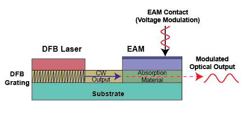
Figure 6. Electro-Absorption Modulator (EAM) integrated into a DFB Laser Chip
ACOUSTO-OPTIC MODULATION
AOM (Figure 7) is a method to modulate the intensity of a laser output using a sound wave to manipulate the refractive index of a crystal or glass material. An AOM system includes an acousto-transducer piezoelectric that applies the modulation to the sound wave using an electrical signal. The resulting sound wave scatters some of the light and decreases the intensity of the transmitted and measured signal or 0-Order. The light is diffracted from the generated sound waves, exhibiting a Bragg diffraction, changing the transmission intensity. AOM is one of the more complicated technologies, but is still an effective way to modulate a laser diode especially for high optical power applications and high performance fiber modulation. AOM can be more expensive due to the crystal material required, especially for larger beam radius sizes.
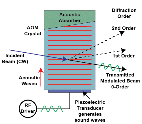
Figure 7. Acousto-Optic Modulator
Methods & Comparison
Careful consideration should be taken to decide which method to use to modulate a laser diode for a specific application. Although both types of modulation deal with continuous wave laser diodes, the location of the modulation before or after the laser output determines the advantages and disadvantages.
Often, external modulators are more expensive. Although external modulation does have the benefit of faster speeds (higher bandwidths), the cost and complexity of the laser setups are also much higher. On the other hand, direct modulation is simple and can be implemented through a laser driver. No complex circuitry is needed to modulate the injection current as this is included in most laser driver modules or instruments. While external modulation can achieve speeds up to 100 GHz, direct modulation is limited to a few GHz, usually high MHz, due to laser diode physical limitations. For simple design and cost sensitive projects, direct modulation can be the solution. For higher modulation speeds (especially communication applications), external modulation is preferred.
Issues & Solutions
There are a few problems that can arise when modulating a laser signal. Below are a few common issues and solutions or recommendations, mainly for direct modulation.
- Exceeding Bandwidth – When directly modulating a laser, exceeding the bandwidth can cause distortions and output attenuation. Check with the laser driver and laser diode datasheets to ensure you are well below the listed modulation bandwidth.
- Oscillation Frequency – If the laser is modulated at or around the oscillation frequency, relaxation oscillations can occur. Avoid the oscillation frequency of the laser for better signal response and reduced oscillation around the setpoint.
- Noise – A laser driver with high noise can affect the clean output of the modulated laser. Select a low noise driver to ensure electronic noise does not propagate through the optical system.
- High Current – High current operation as well as high modulation frequencies can expose underlining issues of the laser design. Careful selection of wires, power supplies, and capacitor banks can solve some of the issues created at higher currents (>10 A).
Technical Note TN-LD04: Laser Diode System Design Considerations for Modulation at >10A has more information on this topic. - Inductance – Signal integrity can be reduced from inductance in the electrical circuits opposing the change in current. The rate of change of current impacts the ability of the driver to maintain precision current control. Choosing the shortest and heaviest gauge wires possible reduces the inductance of the system.
- Wiring – Technical Note TN-LD03: PLD Series Laser Driver Modulation Recommendation highlights the effects of long, unfiltered, and untwisted wires. As stated before, proper wire selection (short, filtered, and twisted) can help improve the response of the laser output to the modulation signal input for direct modulation.
- Power Supply – When modulation occurs, the driver draws different current levels from the power supply as the modulation waveform passes through the system. If the modulation is too fast or too large, the power supply can become the limiting factor of the system. Ensure that the power supply and modulation speeds are compatible by referring to the transient speed specification in the datasheet.
Glossary
Analog Modulation: A continuous and smooth signal that is limited to a range of values.
AOM: Acousto-Optic Modulation
Digital Modulation: A set of finite, discreet values.
Direct Modulation: Current is modified with the desired signal before reaching the laser diode, usually with a laser diode driver.
EAM: Electro-Absorption Modulation
EOM: Electro-Optic Modulation
External Modulation: Modulation signal is imposed onto the laser signal after the laser light is generated.
Fall Time: Time for the optical or electrical output to fall from 90% to 10% of its set or maximum value.
Modulation: Current or voltage varies with time to vary the output signal from the laser.
Relaxation Oscillation: Initial overshoot in optical output power is followed by a few cycles of damped oscillation before stabilization.
Rise Time: Time for the optical or electrical output to rise from 10% to 90% of its set or maximum value.
Turn-on Delay: Delay of laser output when injected with current until the injection current surpasses the threshold for lasing.
References
- Marketteck, Overview of Modulated and Pulsed Diode Laser Systems, Application Note. https://www.markettechinc.net/wp-content/uploads/2018/05/Modulated-and-Pulsed-Diode-Lasers.pdf
- https://www.physics.purdue.edu/webapps/index.php/course_document/index/phys570P/1684/25/14317
- Riaziat, M. L., Introduction to High-Speed Electronics and Optoelectronics. Wiley, 1996.
- Minasian, R. A., Modulation and Demodulation of Optical Signals. Encyclopedia of Modern Optics (2005), 129-138.
https://doi.org/10.1016/B0-12-369395-0/00667-9
