What is a laser diode driver?
In the most ideal form, it is a constant current source, linear, noiseless, and accurate, that delivers exactly the current to the laser diode that it needs to operate for a particular application. The user chooses whether to keep laser diode or photodiode current constant and at what level. Then the control system drives current to the laser diode safely and at the appropriate level. The block diagram in Figure 1 shows a very basic laser diode driver (or sometimes known as a laser diode power supply). Each symbol is defined in the table below. Each section is described in detail below. Laser diode drivers vary widely in feature set and performance. This block diagram is a representative sample, meant to familiarize the users with terminology and basic elements, not an exhaustive evaluation of what is available on the market.

Figure 1: Laser Diode Driver Schematic
| Symbol | Name & Brief Description |
|---|---|
 |
Laser Diode: The function of the Laser Diode Driver is to provide current to the laser diode. The wavy arrows indicate light exiting the package. A huge array of applications exist for laser diodes. These can include spectroscopy, remote sensing, medical diagnostic & analytical equipment, particle sizing & counting, welding & materials processing, and a myriad of other applications. It often is abbreviated as LD. |
 |
Photodiode: Sometimes, a monitor photodiode is integrated into the laser diode package. It produces a current somewhat proportional to the output laser diode optical power. Each laser diode package is different and usually the photodiode transfer function varies widely. The wavy arrows indicate light entering the package. It often is abbreviated as PD. |
 |
Feedback Mode: Most laser diode drivers will allow control based on either laser diode current or photodiode current. If laser diode current is used as feedback, the control system will try to keep it constant. The output of the Adjustable Current Source will not vary. This is called Constant Current Mode (or CC mode). If photodiode current is used as feedback, the control system will try to keep the photodiode current (and by extension – laser diode optical power) constant. The output of the Adjustable Current Source WILL vary to keep the optical power level the same. This is called Constant Power Mode (or CP mode). |
 |
Adjustable Current Source: Current flows through the laser diode as regulated by the current source. |
 |
Ammeter: Current is measured through the laser diode or photodiode and translated into a voltage. IMON represents the current through the laser diode. PMON represents the current through the photodiode. |
 |
Summing Amplifier: These are used to measure the difference between setpoint and actual current, or to sum the onboard setpoint trimpot with an external analog modulation signal. |
 |
G(Power): This function represents how the error between setpoint and actual photodiode current is modified to make an electronic signal that appropriately drives the Adjustable Current Source to keep error to a minimum. It is used during Constant Power mode operation. |
 |
G(Current): This function represents how the error between setpoint and actual laser diode current is modified to make an electronic signal that appropriately drives the Adjustable Current Source to keep error to a minimum. It is used during Constant Current mode operation. |
 |
Modulation Input: An analog signal (e.g. a sine wave, triangle wave scan, or square wave) can be input to the laser diode driver. This voltage signal is related to the actual current or power output by a transfer function. |
 |
Onboard Setpoint Circuit: Since setpoint is application specific, it must be adjustable by the user. Typically, laser diode power supplies integrate an adjustment mechanism, such as a trimpot. |
 |
Limit Circuit: This section of the laser diode driver is key to protect the laser diode. The user sets the limit current based on the operating parameters of the laser diode (typically well below damage threshold). An Active Current Limit will shut off the laser diode current if the control system drive exceeds this current limit setting. |
 |
Safety Functions: While laser diode reliability has significantly improved over the years, a laser diode is still susceptible to damage in a variety of ways. These safety functions protect the laser diode as much as possible. |
 |
VDD: This symbol is used to refer to the external power supply that feeds the control electronics. In an instrument, this is not seen by the user. In a component or module, the user chooses how to power the control electronics. Usually this is low voltage – 3.3 to 5 V DC. |
 |
VS: This symbol is used to refer to the external power supply that feeds the Adjustable Current Source (or output stage) electronics. In an instrument, this is not seen by the user. In a component or module, the user chooses whether to tie the control electronics to the output stage or separate them so higher compliance voltage can be delivered. This is a DC voltage. |
| IMON: This symbol represents the laser diode current monitor voltage. Laser Diode current is related to this voltage by a transfer function given in the laser diode driver datasheet. | |
| PMON: This symbol represents the photodiode current monitor voltage. Photodiode current is related to this voltage by a transfer function given in the laser diode driver datasheet. Photodiode current and laser diode output power are related by a transfer function given in the laser diode datasheet. |
Laser Diode Current Source: One key section of a laser diode driver is the Adjustable Current Source. It can also be known as the Output Stage. This section responds to the Control System section by driving current to the laser diode. In the block diagram, the laser diode is between supply voltage and the current source. Other laser diode drivers put the laser diode between the current source and ground. Depending on the laser diode configuration and grounding, one approach may be better than the other. This is the section where the user wires the laser diode and/or photodiode into the circuit.
Control System: User inputs include the limit setpoint (in terms of maximum laser diode current allowed to the laser diode), the operating setpoint, and whether the control variable is laser diode current or photodiode current. Additionally, if a remote setpoint is required, an Analog Modulation Input is usually available.
- Setpoint: This is an analog voltage into the system. It can be created by a combination of onboard adjustment and the modulation input. In some cases, the modulation input sums with the onboard setting. In other cases, it subtracts from the onboard setting.
- Error Generation: To know how the system is functioning, the Actual current level is compared to the Setpoint current level. These two voltages are subtracted and the result is called the “Error.” In the case of a laser diode driver, the actual current level can come from either the laser diode or the photodiode. If laser diode current is used as feedback, the control system will use the Error signal from the laser diode current. The output of the Adjustable Current Source will not vary. This is called Constant Current Mode. If photodiode current is used as feedback, the control system will try to keep the photodiode current (and by extension – laser diode optical power) constant. The output of the Adjustable Current Source WILL vary to keep the optical power level the same. This is called Constant Power Mode.
- Control Function: This converts the error signal into a control signal for the Laser Diode Current Source. It is not the same for Constant Power or Constant Current mode.
- Limit Circuit: One way to damage a laser diode is to drive too much current through it. Each laser diode datasheet will specify a maximum operating current. Exceeding this current will damage the laser diode. To avoid this, a limit circuit is included in the laser diode power supply. The user determines the maximum setting and the output current is kept from exceeding that level. Some limit circuits cap the current at the max level and keep operating. An Active Current Limit circuit will disable the laser diode driver current.
- Safety features: These vary widely between laser diode drivers. Worldwide, governmental regulations require a few basic elements for the more powerful laser systems. First, there must be a time delay between application of electrical power and lasing. Second, there must be a way to interlock protective housings or entry doors, so that if the housing or door is opened, the laser shuts off. Laser diodes are sensitive to thermal shock so a slow-start circuit is usually integrated. For DC powered drivers, an output shutdown when the voltage droops and threatens control integrity is called Brownout Protection. Another valuable feature can protect the laser diode against ESD shocks or transients from the power supply.
- Power: Power must be provided to the control electronics and current source. This can take the form of a DC power supply (some drivers use single supply inputs, others use dual supplies), or an AC input connector and cable. In some cases, where higher voltage is required to the laser diode, separate DC power supply inputs may be available to power the control electronics from a low +5 V supply and the laser diode from a higher voltage supply.
What is the difference between an instrument, a module, and a component?
Usually price, feature set, and size. An instrument typically has a front panel with knobs and button adjustments and some form of display to track how the laser diode is operating. These can all be automated with computer control via USB, RS-232, RS-485, or GPIB. An instrument is usually powered by AC, not a DC power supply. By our definition, a module doesn’t include the display or power supply, and has the minimum required adjustments. To monitor status, an external volt meter measures voltage and the module datasheet provides a transfer function to convert the voltage to actual laser diode current or photodiode current. A component is further stripped down, with no moving parts. External resistors or capacitors set operating parameters. Safety features are common to all three forms. Usually modules can sit on a benchtop or be integrated into a system using cables. Components mount directly to a printed circuit board (PCB) with plate-through or surface mount (SMT) pins. Two rows of pins are referred to as DIP packaging (dual-in-line), while a single row of pins is called SIP packaging (single-in-line).
A variety of off-the-shelf controllers are available in both instrument and OEM packages. Some vendors are blurring the boundaries, for example, offering USB control of components as mini-instruments.
Packaging of components and modules includes proper heatsinking of the circuit elements (or guidance on how the device should be heatsunk) and usually includes the appropriate cabling to the laser diode and power supply. Instruments include a power cord and user access inside the case is not necessary.
Threshold Current: A specification of the laser diode. At this current emission changes from spontaneous (LED like) to stimulated and coherent light is produced. This value is dependent on the style of laser diode and the temperature of the laser diode case. Telcordia offers four methods of finding the threshold current in SR-TSY-001369.
Forward Current: A specification of the laser diode. Optical power is created with current flow through the laser diode. Once the current exceeds the threshold, the forward current and optical power are directly proportional. The relationship is usually given by a graph.
Forward Voltage: A specification of the laser diode. Forward Voltage changes as Forward Current changes, similar to a diode curve. Forward Voltage is used to determine the minimum DC power input level to a module or component to sufficiently drive the laser diode. It is also used to determine how power is dissipated in the load versus in the driver itself.
Constant Current Mode: Feedback controlling the current source is the actual current through the laser diode.
Constant Power Mode: Feedback controlling the current source is the actual current through the photodetector.
Modulation Bandwidth: This can be specified for a sine wave or square wave. It is typically the frequency at which an input signal is half the size of the original signal (3 dB point).
Depth of Modulation: This is specified in percentage. 100% depth of modulation means the maximum peak-to-peak signal allowed in the analog modulation input is repeated on the output current without distortion. Depth of modulation decreases as frequency increases.
Disable: When output current is disabled, all safety mechanisms are usually set to an initial power on state and only a residual leakage current is delivered to the laser diode.
Leakage Current: Ideally, when a laser diode driver is turned off, no current flows through the diode. In practice, power is not turned off, but the laser diode is disabled. The circuitry disables the Control System, not the Current Source. Small amounts of current can still flow through the diode. If ESD protection is in parallel with the diode, all residual current should bypass the diode when the current source is disabled. Laser diodes are typically not hot-swappable. Remove the laser diode only when all power is off to the system following proper ESD precautions.
ESD: Electro-static Discharge. The “zap” one feels crossing a carpet & touching a metal door knob is the most common example of ESD. Laser diodes are sensitive to ESD. A discharge that a human doesn’t feel is still enough to damage a laser diode. Proper ESD precautions should be followed whenever handling a laser diode or other ESD sensitive electronic equipment.
DVM: Digital Volt Meter, a meter that monitors voltage.
Ammeter: A meter that monitors current.
Internal Power Dissipation: With a linear current source, some of the power delivered by the power supply goes to the laser diode, and some is used in the laser diode driver. The Maximum Internal Power Dissipation of a driver is the limit past which thermal damage to internal electronic components is possible. Designing a laser diode system includes choosing the power supply voltage. If a 28 V supply is chosen to drive a diode whose forward voltage is 2 V, 26 V will be dropped across the laser diode driver. If the driver is running at 1 Amp, the internally dissipated power will be V * I or 26 * 1 = 26 Watts. If the internal power dissipation specification is 9 Watts, the Current Source components will overheat and fail. Wavelength provides online Safe Operating Area Calculators for all components and modules to simplify this design choice.
Compliance Voltage: The Current Source has an associated voltage drop across it. Compliance Voltage is the power supply voltage minus this internal voltage drop. It is the maximum voltage that can be delivered to the laser diode. It is typically specified at full current.
Current Limit: In the laser diode datasheet, Maximum Forward Peak Current will be specified at an ambient temperature. Above this current, the laser diode will be damaged. At higher temperatures, this maximum value will reduce. The Current Limit is the maximum current the Current Source will deliver. An Active Current Limit will trigger the control system to disable the current if Current Limit is exceeded. The Current Limit can be set below the laser diode maximum current, and used as a tool to minimize the Internal Power Dissipation of the laser diode driver.
Load: For a laser diode driver, the load consists of the laser diode and / or the photodiode.
IMON: This is an analog voltage proportional to the laser diode current. Transfer functions are provided in individual driver datasheets.
PMON: This is an analog voltage proportional to the photodiode current. Transfer functions are provided in individual driver datasheets.
RPD: This is a common term used to refer to a resistor in series with the photodiode. Measure the voltage across this resistor to determine photodiode current. [Ohms Law: V = I * R].
VSET: This is a common term used to refer to the Analog Modulation Input signal. V indicates a voltage signal while SET indicates its purpose: control system setpoint. It can also be called MOD or MOD IN.
What are typical specifications and how do I interpret them for my application?
At present, each vendor conducts their own testing and there is no standard for measurement. Once you identify a solution for your application, it is critical to test the product in your application to verify operation. Here are some of the definitions Wavelength uses and how to interpret the specifications in your design.
Input Impedance: This is specified for analog voltage inputs such as VSET or MOD IN. At higher frequencies, the relative value of the impedance of the source and the impedance of the input pin matter. The voltage of the modulation signal may be reduced if the values are mismatched. The fraction of the signal reflected at the interface is given by:
(ZL – ZS)/(ZL + ZS) where ZL is the impedance of the input pin and ZS is the source impedance.
Noise: For a laser diode driver, the noise of the output current is usually given as a single number in microAmps. A more correct representation of noise is mA / √Hz, or current noise across a given bandwidth.
Bandwidth: This is specified for a sine wave. Where the peak-to-peak amplitude of the sine wave is half the magnitude of the signal input at the Analog Modulation Input (3 dB point).
Rise Time: After the initial delay and slow start sequence, if a square wave is applied at the Analog Modulation Input, the Current Source will respond to change this quickly. This can also be called ON time.
Fall Time: When the Current Source is disabled, the current level through the diode will fall to residual levels within this time. This can also be called OFF time.
Depth of Modulation: The response of the Current Source will change as modulation frequency increases. At low frequencies, a full rail-to-rail signal can be input and the Current Source will follow along exactly. This is 100% depth of modulation. At higher frequencies, the peak-to-peak values will no longer get all the way to the rail. At 90% depth of modulation, a 5 V peak-to-peak input signal will result in a 4.5 V peak-to-peak change in IMON.
Operating Temperature Range: Electronics are designed to operate properly across a designated temperature range. Outside of the minimum and maximum temperatures, damage can occur or behavior can change. The operating range that Wavelength specifies is coupled with the Maximum Internal Power Dissipation specification. Above a certain ambient temperature (usually 35°C or 50°C) maximum internal power dissipation derates to zero at the maximum operating temperature.
Operating Voltage Range: In some laser diode drivers, two input voltages can be used – one to power the control electronics (VDD) and one to provide higher compliance voltage to the laser diode (VS). Typically, the control electronics operate on lower voltages: 3.3 to 5.5 V. Exceeding this voltage can damage elements in the Control or Power sections. The Current Source (or Output Stage) is designed for higher voltages (such as 30 V with the PLD family of laser diode drivers). This specification needs to be considered in conjunction with the drive current and power delivered to the load to make sure the design does not exceed the Maximum Internal Power Dissipation specification. For example, the PLD5000 is specified to operate up to 5 Amps at 30 V input. Its maximum internal power dissipation is 15 Watts. If 28 V is used to power a laser diode which drops 2 V, 26 V will drop across the PLD5000. At 26 V, the maximum current within the safe operating range is less than 15 / 26 or 0.576 Amps. Driving more than that current will overheat the Output Stage components and potentially irreversibly damage the driver.
Monitor vs. Actual accuracy: IMON and PMON signals are analog voltages proportional to laser diode current and photodiode current, respectively. The accuracy of the actual currents relative to the measured values is specified in the individual driver datasheets. Wavelength uses calibrated, NIST traceable hardware to ensure this accuracy specification.
Separate Monitor & Power Grounds: One high power ground is designated to connect to the power supply on any laser diode driver. Several low current grounds are located amongst the monitor signals to minimize offsets and inaccuracies. While high and low current grounds are tied internally, for best results, use a low current ground with any monitor.
Linear or switching power supplies for components and modules: Linear power supplies are relatively inefficient and large compared to switching power supplies. They are, however, low noise. If noise is critical to your system, you can try a switching power supply to see if the switching frequency affects performance anywhere in the system.
Laser Diode Types:
Wavelength defines three different laser diode / photodiode pin configurations. Some laser diode drivers are universal, while others are specific to the wiring of the laser diode. These are clearly identified in each laser diode driver datasheet.

Grounding with modules and components:
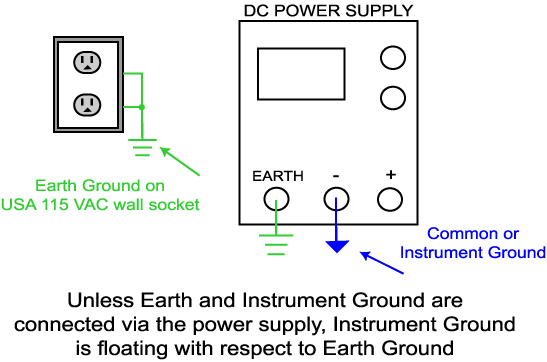
Some laser diode packages short either pin of the laser diode to the case, which may connect the pin to earth ground through system hardware. Special attention to the details of grounding will ensure safe operation. The following definitions and options assume the power supply ground is floating or isolated from earth ground:
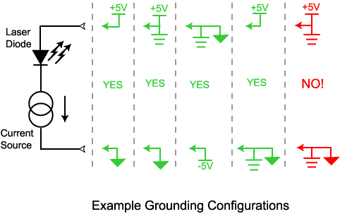
Additionally, if you combine a laser diode driver with a temperature controller, you may need to use separate power supplies. If the TEC or thermistor is connected to the laser diode, you may need to separate grounds, using a power supply for each controller and letting each power supply float independent of the other.
Wavelength designs laser diode drivers and manufactures them at a facility in Bozeman, Montana, USA. For a listing of the current laser diode driver selections, click here.
Useful sites:
External links are provided for reference purposes. Wavelength Electronics is not responsible for content of external sites.
