What is Bandwidth?
Electronic signals can form a pattern or repeat over a cycle. Each individual repetition time is called a Period (T). The period can be any measure of time, such as second, an hour, or a day. The repetition of each period over time is called Frequency (f) and determined using this formula: f = 1/T. The number of events that happen in one second is described as frequency in the units called Hertz (Hz). For example, if a signal cycles through 2 times in one second (one cycle in half a second), then frequency is determined like this:

Equation 1. Frequency Calculation
The range of frequencies that a system passes through or rejects is given by the system bandwidth. For example, a system, as defined by the following graph, passes DC and other increasing frequencies, and then starts rejecting frequencies gradually until it rejects higher frequencies consistently.
The bandwidth is often defined by the frequency that is half-attenuated, or at the midpoint between the most output and no output. This is called the 3 dB bandwidth, also known as the cutoff frequency.
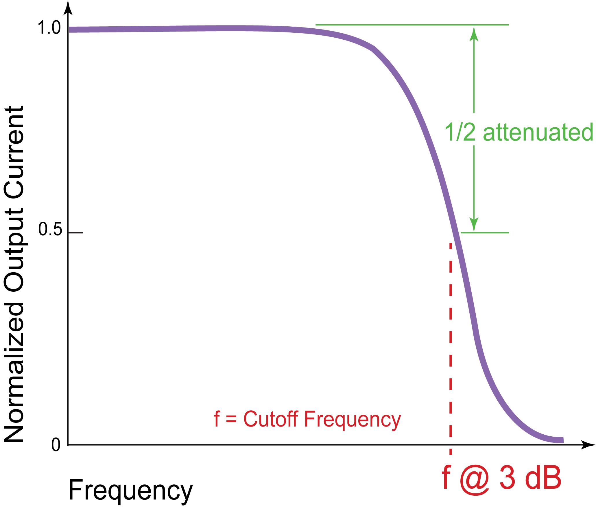 Figure 1. Bandwidth Cutoff Frequency
How is Bandwidth Measured?
The frequency response of a system is usually specified with a single frequency sinewave as input. At Wavelength, we specify the 3 dB bandwidth of a laser diode driver as the sinusoidal frequency that is half-attenuated through the controller.
To measure the bandwidth of a driver, put in a sinusoidal setpoint that peaks at one volt, then increase the frequency of the sinewave until only half a volt of equivalent setpoint comes out. That’s the 3dB bandwidth.
What are Rise and Fall Times?
Rise time is how quickly an electronic signal changes from 10% of maximum to 90% of maximum. Fall time is basically the opposite, the speed with which the signal changes from high level to low.
I’m Modulating with a Square Wave. What Does It Look Like at the Current Output?
A square wave is formed by overlaying several sinusoidal frequencies of varying strength. If we overlay the main signal and its odd harmonics, a rough square wave is formed. The more harmonics that are used, the more distinct the square wave becomes.
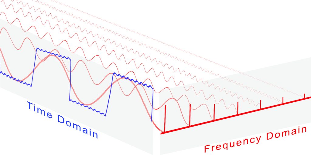
Figure 2. Time Domain and Frequency Domain
To represent a time-based signal shape in the frequency domain, a Fourier Transform is used. Essentially, any time based signal can be represented as a sum of various frequencies at various strengths, offsets, and rotation speeds. The transform equation for a square wave is:
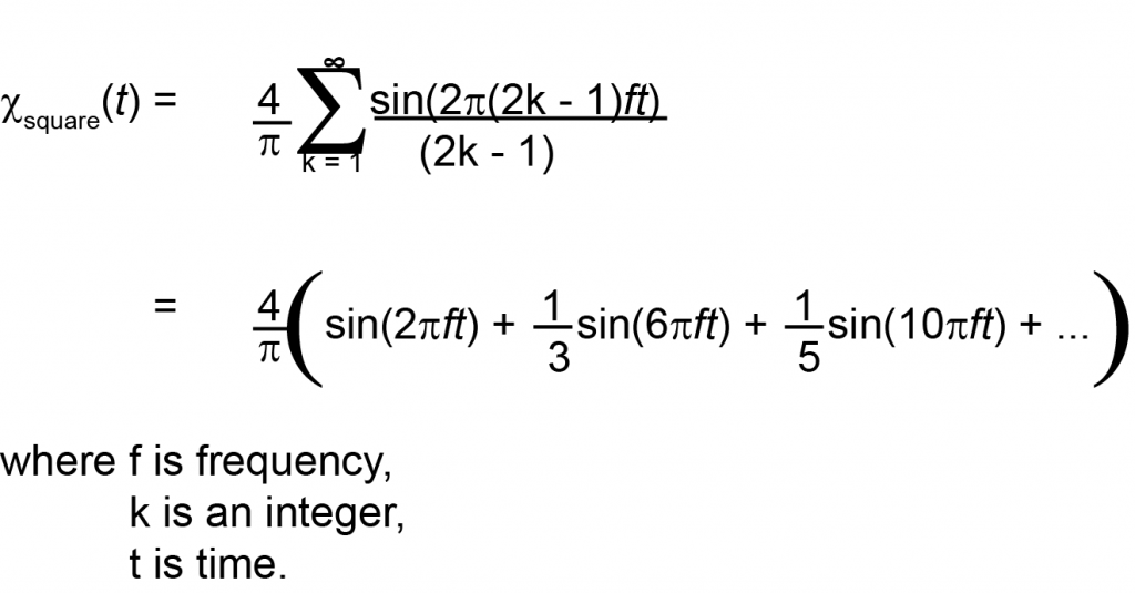
Equation 2. Fourier Transform of a Square Wave
A square wave in the frequency domain looks like a sum of odd frequencies:
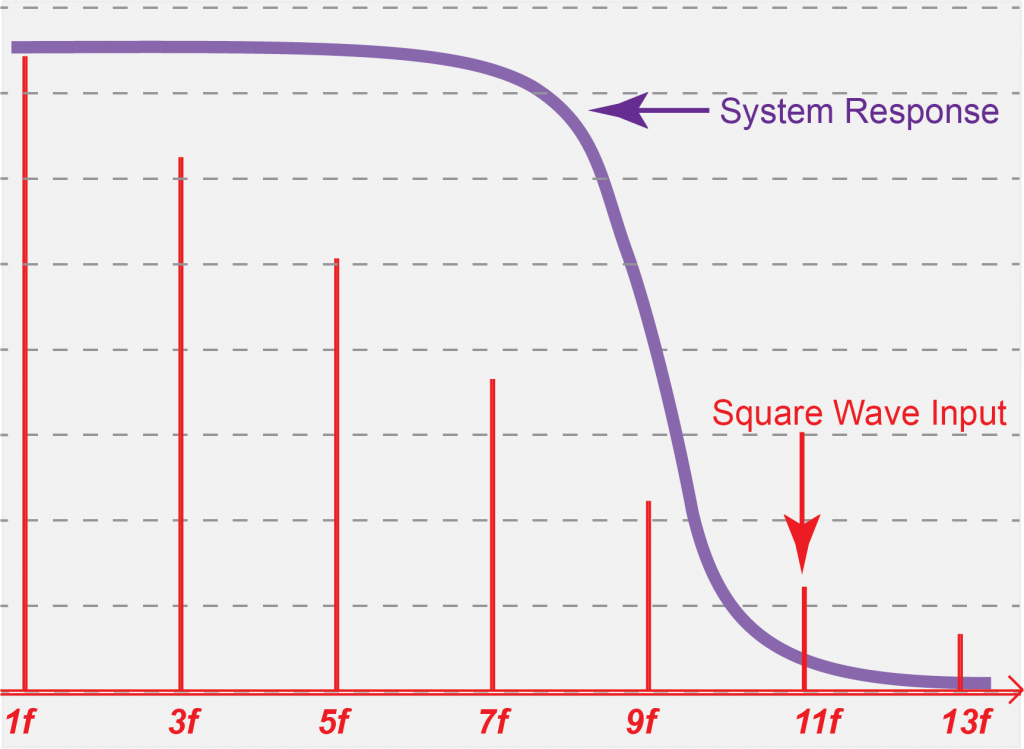
Figure 3. Square Wave in Frequency Domain Overlaid by the Frequency Response of a Bandwidth Limited Driver
When system bandwidth is overlaid with the setpoint input square wave frequencies, the upper harmonics are lost. The output current will lose the square edges when setpoint frequency is increased, as shown in Figure 4 and Figure 5.
The shape of the output depends also on the system rise / fall times. The output current will follow a step input at its specified rise time maximum rate.
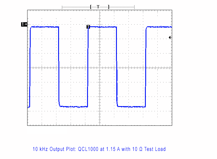
Figure 4. Example System Where Output Matches Input at 10 kHz
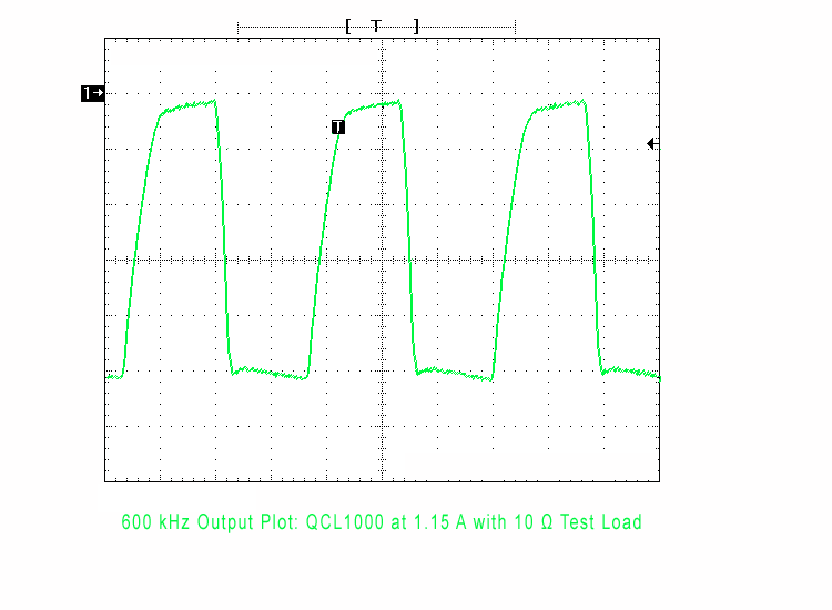
Figure 5. Same System as in Figure 4, Where Output is Attenuated and Square Edges are Lost at 600 kHz
Conclusion
Circuits are often given a bandwidth specification. This indicates that the circuit will not pass all frequencies in a time varying setpoint signal. Sinewaves through this system will be attenuated; square waves and others represented by summations of frequencies will change shape as the base frequency increases.
Rise and fall times can also limit how fast a driver can deliver changing current to the load. Evaluation of output current frequency response can be critical to the practical success of a project.

