What is a Test Load?
And why do I need to use one? How and when should I use one, and how do I know it’s working?
These are questions our technical support staff are asked regularly, along with how to set up a test load and which load is best for each Wavelength product series. The discussion below will cover that information, as well as what equipment you need, when to use Constant Current or Constant Power modes, and how to prepare your equipment for the actual load. We will address using test loads with only temperature controllers and laser diode drivers.
A test load is a tool for testing a device or system and measuring a response without using the application load and, ideally, the test load should closely mimic the eventual load. Using a test load is a good way to get familiar with a controller, test how it works, and make sure it operates as expected before the final set up. For example, laser diodes can be expensive and are usually not readily available, so destroying one during set up can be both costly and time consuming. To avoid this hazard, the system can be set up with a test load and tried before attaching the laser diode. A test load can also help show, through monitoring, what happens when limits are exceeded. Additionally, if you are having a problem while using a system, a test load can help troubleshoot any problems.
NOTE: While this Application Note will address questions particular to using a test load, it is not meant to replace the product datasheets, which contain all of the equipment, instructions, calculations, and troubleshooting information needed to successfully use the products.
Why Use a Test Load for Laser Diode Set Up?
Using a test load verifies that the rest of the equipment is set up correctly and in working order prior to attaching the laser diode. It also allows you to become familiar with trimpot rotation and sensitivity, to correctly set up wiring and monitoring, and to troubleshoot any problems that may arise.
The test load processes that follow verify the current output in Constant Current mode and the limits are set up and can be monitored. When setting limits, you are able to see when the limits are reached and can adjust the set up of the controller accordingly. In Constant Power mode, the test load allows you to set up and monitor the simulated photodiode current.
The following equipment is necessary when setting up a test load:
- Laser diode driver or driver with evaluation board
- Multimeter, set to read voltage
- Oscilloscope (optional, needed only if testing analog modulation input)
- Signal generator (optional, needed only if testing analog modulation input)
- Test load, for examples, see Figure 1 for Constant Current and Figure 2 and Figure 3 for Constant Power
- 5 V Power supply
- Connection cables or wires
About Test Loads in Constant Current Mode
Using Constant Current when setting up the test load allows you to set the Current Limits and Current Setpoint. Wavelength trimpots are 12-turn trimpots and are turned counter clockwise (CCW) for off and clockwise (CW) for on, the exception being the LDTC 2/2 E & O, where they are reversed. Consult the product documentation to verify the direction before proceeding.
NOTE: The 12-turn trimpots continue to turn after the 12th turn has been reached. Any additional turns do not vary the resistance.
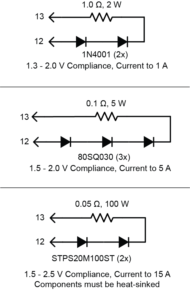
Figure 1: Example Test Loads for a Laser Diode in Constant Current Mode
Set Up the Laser Diode Test Load Using Constant Current Mode
- Attach a test load between the Laser Diode Anode (LDA) and Laser Diode Cathode (LDC) of the laser diode driver (see Figure 1).
- Set the driver in Constant Current mode.
- Connect the multimeter, in voltage mode, between the Current Monitor (IMON) and common Ground (GND) pins.
- Turn the Current Limit trimpot fully off, usually 12 full rotations counterclockwise (CCW).
- Turn the Current Setpoint trimpot fully on, usually 12 full rotations clockwise (CW).
- Attach a 5 V power supply. A higher voltage power supply can overheat the controller when using test loads.
- Enable the unit.
- Use the transfer function calculation in the datasheet to determine the IMON reading at the desired current limit.
- Increase the Current Limit by turning the trimpot, usually CW, until the desired maximum IMON limit voltage is reached and then stop. The Current Limit is now set.
- Use the transfer function to calculate the IMON voltage at the desired operating current.
- Decrease the Current Setpoint by turning the trimpot, usually CCW, until the current starts to go down and the IMON voltage value is reached.
- OPTIONAL: Wire a signal generator to the analog modulation input. The datasheet has the transfer function equations.
- OPTIONAL: Replace the multimeter across the IMON and GND with an oscilloscope to monitor the output current variation with time.
- Once the test load limits have been set and you are familiar with the system, return the Current Setpoint and Current Limit trimpots to their respective OFF positions (usually 12 turns CCW).
NOTE: If testing a load in Constant Power mode, do NOT follow this step.
About Test Loads in Constant Power Mode
To test or understand the photodiode feedback and current monitor circuits, you can replace the constant current test load with one specific to constant power mode. The circuits in Figure 2 vary simulated photodiode feedback current as laser diode output current changes.
The values in Table 1 are based on the following:
- The voltage at PMON will be approximately 1 V if the setpoint is 1 V in CP mode.
- A 5 V power supply is used
- The laser diode current (ILD) will be approximately one half the maximum capacity of the laser diode driver model.
NOTE: If the current limit is set below half of the maximum capacity of the laser diode driver, the PMON voltage and feedback will be lower.
To decrease ILD, but keep PMON at approximately 1 V, reduce RE.
To decrease PMON for a given laser diode current, increase RE. The new PMON will be proportional to the change in RE.
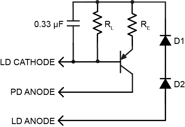
Figure 2: Test Load for a Laser Diode (Type A/B) in Constant Power Mode
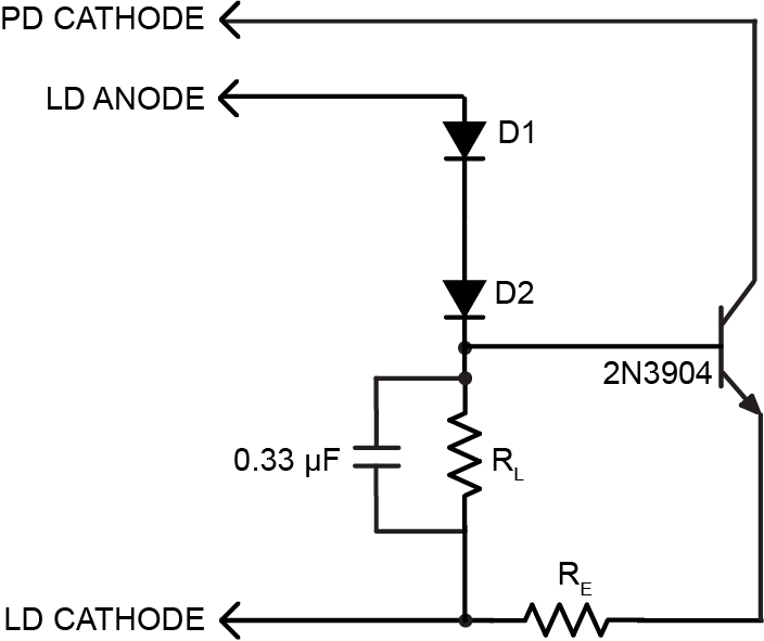
Figure 3: Test Load for a Laser Diode (Type C) in Constant Power Mode
Set Up the Laser Diode Test Load Using Constant Power Mode
- With the settings maintained from testing in Constant Current mode, attach a test load to the LDA, LDC, and the Photodiode Anode (PDA) (see Figure 2 and Figure 3).
NOTE: For any laser package, confirm the laser type before testing. - Set the driver in Constant Power mode and in the appropriate PD range to support the PDI in the table below.
- Connect the multimeter, in voltage mode, between the PMON and common GND pins.
- Attach a 5 V power supply. A higher voltage power supply can overheat the controller when using test loads.
- Enable the unit.
- When the Constant Power mode testing is complete, return the Current Setpoint and Current Limit trimpots to their respective OFF positions (usually 12 turns CCW).
| MODEL | RL (Ω) | VRL (V) | RE (Ω) | D1, D2 | PDI |
|---|---|---|---|---|---|
| FL591FL | 8.8 | 1.1 | 1000 | 1N4001 | 500 µA |
| FL593FL | 8.8 | 1.6 | 1000 | 1N4001 | 500 µA |
| LDD200P -1 & 2P | 16 | 1.6 | 1000 | 1N4001 | 1.0 mA |
| LDD200P-3P | 16 | 1.6 | 2000 | 1N4001 | 50 µA |
| LDD400P -1&2P | 8 | 1.6 | 1000 | 1N4001 | 1.0 mA |
| LDD400P-3P | 8 | 1.6 | 2000 | 1N4001 | 500 µA |
| LDTC0520 | 4.4 | 1.1 | 1000 | 1N4001 | 500 µA |
| LDTC1020 | 2.2 | 1.1 | 1000 | 80SQ035 | 100 µA |
| LDTC2/2 (E or O) | 1.1 | 1.1 | 4990 | 80SQ035 | 200 µA |
| PLD200L | 16 | 1.6 | 4990 | 1N4001 | 200 µA |
| PLD500 | 6.4 | 1.6 | 4990 | 1N4001 | 200 µA |
| PLD1250 | 2.56 | 1.6 | 4990 | 80SQ035 | 200 µA |
| PLD5000 | 0.64 | 1.6 | 4990 | 80SQ035 | 200 µA |
| PLD6500 | 0.49 | 1.6 | 4990 | 80SQ035 | 200 µA |
| PLD10000 | 0.32 | 1.6 | 4990 | STPS20M100ST | 200 µA |
| PLD12500 | 0.256 | 1.6 | 4990 | STPS20M100ST | 200 µA |
| PLD5K-CH | 0.64 | 1.6 | 4990 | 80SQ035 | 200 µA |
| PLD10K-CH | 0.32 | 1.6 | 4990 | STPS20M100ST | 200 µA |
| PLD12.5K-CH | 0.256 | 1.6 | 4990 | STPS20M100ST | 200 µA |
| WLD3343 or HB | See NOTE below | ||||
| WLD3343-3A | See NOTE below | ||||
NOTE: Settings for the WLD laser diode driver family are not given. This is because the photodiode gain resistor is external to the WLD. Contact the factory for assistance in setting up a constant power test load for the WLD.
About Temperature Controllers and Test Loads
Setting up a test load and testing with a temperature controller allows you to test the direction of current flow through the load. It shows the polarity of the controller and whether the sensor feedback is working properly.
The following equipment is necessary when setting up a test load:
- Thermoelectric controller
- 2 Multimeters, one set for voltage and one for current
- 5 V Power supply
- Connection cables or wires
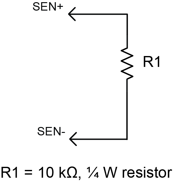
Figure 4: Thermistor Test Load
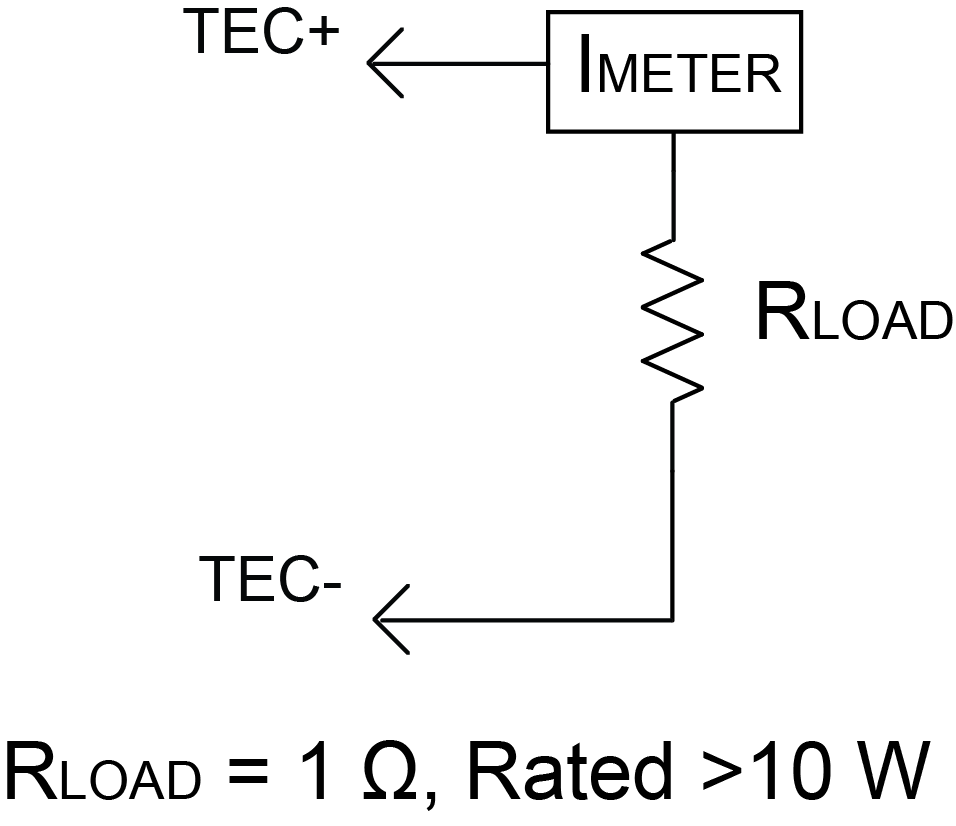
Figure 5: Simulated Thermoelectric Test Load
Set Up the Temperature Controller Test Load
- Attach a 10 kΩ resistor in place of the thermistor (see Figure 4) with a default sensor bias current of 100 µA. The ACT T voltage should read 1 V when the controller has power applied.
- Connect an ammeter in series with the test load resistor (see Figure 5).
NOTE: The positive terminal of the meter must attach to the TEC+ output of the controller and the negative terminal of the meter must attach to the test load resistor. Make sure the ammeter capacity exceeds 1 A. - Attach the voltmeter across ACT T and GND.
- Attach a 5 V power supply to the unit. A higher voltage power supply can overheat the controller when using test loads.
- Turn limit trimpots to OFF (usually 12 turns CCW).
- Enable the unit.
- Turn the SET T voltage to 1.35 V for cooling and turn the Current Limit trimpot until the ammeter reads 1 A. The limit setting can be any value as long as it does not exceed the ammeter capacity or the power rating of the load resistor.
- Turn the SET T voltage to 0.8 V for heating and turn the Current Limit trimpot until the ammeter reads 1 A. The limit setting can be any value as long as it does not exceed the ammeter capacity or the power rating of the load resistor.
- When the testing is complete, return the Current Limit trimpot to the OFF position (usually 12 turns CCW).
In Closing
Once you are comfortable with using the equipment, then it can be powered down and the test load removed. Make sure everything is reset, such as returning the Setpoint trimpot and the Current Limit trimpot to OFF (usually 12 turns CCW) before connecting the application load. Once the actual load is connected, start the set up protocol from the beginning. Be sure to use the appropriate datasheet when setting up the application load.
Using a test load to become familiar with your Wavelength product will help protect your application when setting up the final load. As always, our technical sales engineers are available to help with any questions you may have.

