INTRODUCTION
Laser systems and temperature control systems are comprised of discrete components. While the components (laser, laser driver, temperature controller, power supply, etc.) themselves produce noise that can add to the instability of the design, the connections between these components can contribute to the overall noise as well. Optimizing these component connections will maximize performance and reduce noise levels.
Cabling is a primary means of connecting components. However, cables are prone to picking up electrical interference from the environment and conducting noise from one device to another. Interference, whether electromagnetic interference (EMI) or radio frequency interference (RFI) emitted from electrical devices, can be conducted or reflected. Cables or wires can pick up interference alongside the original signal between the components, or they can reflect it away from the conductor.
A variety of factors are related to cabling optimization, including: leakage resistance, triboelectric and piezoelectric effects, shielding, insulation, grounding, length, and twisting.
SHIELDING & INSULATION
In order to reduce EMI and RFI, cables can be shielded from outside noise. Two conductors can act as noise producers because of the capacitance between them. A Shield surrounds the inner conductors of the cable carrying current, containing EMI or protecting from external EMI. Shielding allows noise or interference to be conducted to the ground (rather than the connected component) or reflected away from the cable. There are two main types of shielding: Foil and Braid.
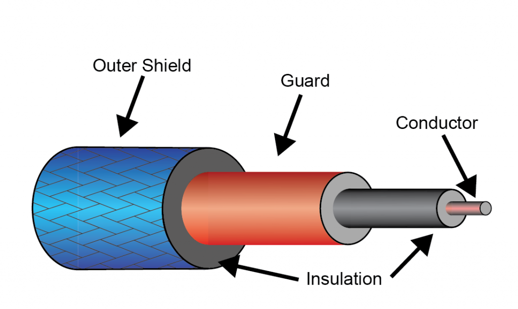
Figure 1: Cable Shielding & Insulation
![]()
Foil shielding uses a thin sheet of aluminum to provide 100% coverage around the conductor. Foil shielding is harder to work with because of its fragile design, so a drain wire is usually included to ground and terminate the shield. Although it can easily break from constant bending and flexing, provides the least shielding effectiveness and high resistance path to ground, it is the lightest and least expensive shielding option. Foil shielding is best for high frequencies. Its small size makes it ideal for individual pairs or multi-pair cables, eliminating crosstalk.
Braid shielding is a woven mesh of bare or tinned copper wires. Because there are small gaps in the mesh, provided coverage is only 65-90% on average. However, it provides a low-resistance path to ground, making it easier to remove unwanted interference. The more robust nature allows trouble-free termination to a connector. The copper design allows a greater shielding efficiency as copper has a higher conductivity value than aluminum. The braid mesh is stronger and can withstand more flexing. The downside to braid shielding is the size, cost, and lower effectiveness at high frequencies.
Another strategy to shielding is some combination of foil and braid shielding (Figure 1). This can provide 100% coverage, 360º termination, and the highest shielding effectiveness. It is common for individual pairs to be shielded with foil while the cable containing multiple pairs is shielded with braid or a combination of both. Size, weight, and cost are all factors to consider when combining types of shielding. Shielding effectiveness also depends on frequency, geometry of the shield, type of field (electric or magnetic), direction of incidence, and polarization.
Insulation is critical to reducing noise, cross-talk, and shorting. Most conductors in cable designs will have insulation around each individual wire and possibly between foil and braid shields. The outside of the cable will be insulated, providing high resistance.
It is important to consider how the cables and the design system connect to ground. Different systems require different grounding connections, but most benefit from single point ground connections. The shield over the cable needs to be grounded, and this is usually accomplished by connectors into the hardware, or ground circuit design. Careful consideration should be made to avoid ground loops, which
can be an additional source of noise. 1 More on ground loops with laser diode drivers and QCL drivers can be found in:
AN-LD08: Manage Ground Loops to Minimize Noise with the QCL Drivers and
AN-LD16: Grounding with Special Laser Diode Configurations.
CABLE LEAKAGE
Low currents require accurate measurements. Current leaking through lower resistance insulation can be reduced using high resistance insulation and guarding.
Figure 2: Guard Configuration
A Guard, shown in Figure 2 in a triaxial cable, is a low impedance point in the design that’s at nearly the same potential as the signal line. This can reduce current leakage in low-current measurements. While triaxial cables are superior to coaxial cables by providing greater interference rejection, they have a higher price tag. The conductor is surrounded by insulation and a guard line. The guard line is
surrounded by the outer shielding (foil or braid), and then the entire cable is wrapped in the outer shell of insulation.
TRIBO- AND PIEZOELECTRIC CURRENTS
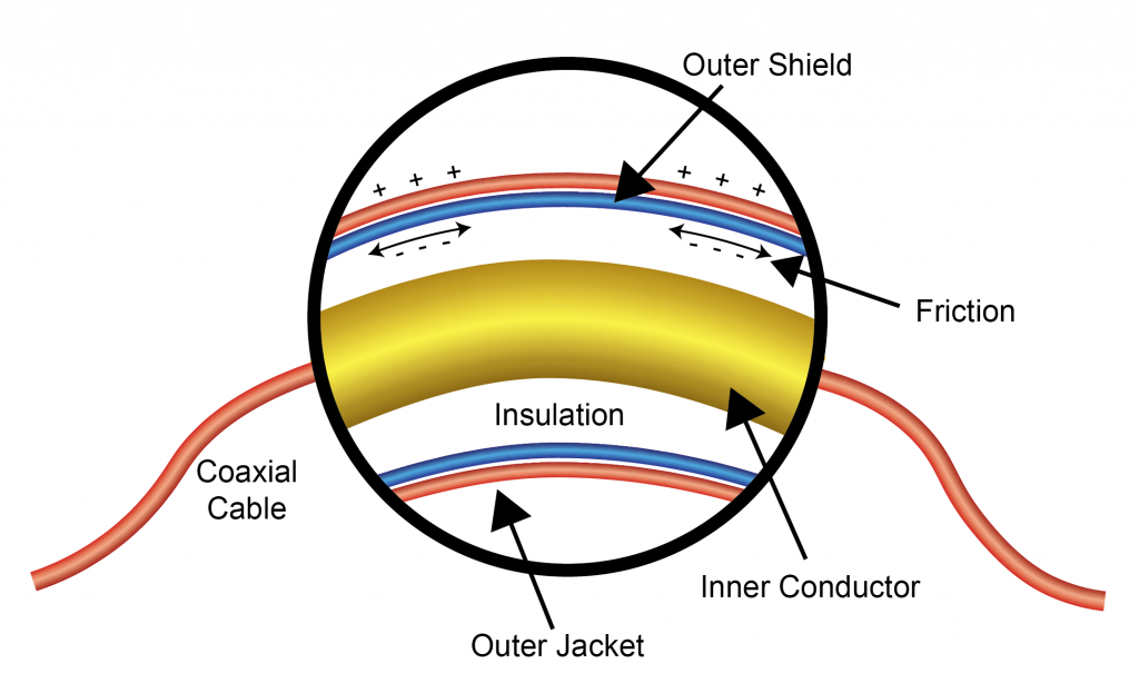
Triboelectric Currents are generated by charges created between a conductor and an insulator due to friction (Figure 3). The act of bending or vibrating the cable will create triboelectric currents. Typical values generated are around 10-8 A. Low noise cables can help reduce this effect by implementing graphite coated polyethylene insulation underneath the outer shield. A cable will not perfectly eliminate the triboelectric effect, but low noise cables can bring the problem to a negligible level (10-15 A).
Figure 3: Triboelectric Effect
Piezoelectric Currents are generated in specific crystalline materials when they are mechanically stressed. This is most common in insulated terminals or interconnecting hardware. Reducing this effect can be accomplished by using insulating materials with minimal piezoelectric and stored charge effects. It is important to choose good insulating materials and have rigid connecting structures.2
Connections of wires and cables need to be made with solid contact. Loose wires can cause serious problems and damage to the laser. High pressure crimp terminal can be used to maintain constant contact with the conductor and the terminal. Always confirm that wires or connectors are properly secured for safely operating the device. Vibrations and movement through magnetic fields can also create additional noise among other issues. To reduce noise induced into the system, use clamps or tie-downs to firmly secure cables.
CABLE LENGTHS
The length and gauge of cable from the power supply or to the laser diode can impact performance through added resistance, inductance, capacitance, magnetic interference, and electrical noise pick-up. The resistance and inductance of the wire can reduce bandwidth or cause the voltage to the device to drop. Shorter cables can help reduce total resistance and inductance of the cable.
Sometimes interference can affect monitoring cables. If the monitor signal jumps above setpoint, it is likely that inductance is present in the monitoring cable from the laser diode. The current through the laser diode is likely still stable, and only the monitoring is affected. Either shorten the length or use twisted pair cables to minimize inductance and eliminate the monitor error.
Longer leads will result in larger voltage drop, wire heating and decreased modulation bandwidth. Wires are twisted to optimize performance. Longer wires can also transmit magnetic interference into the system. Twisted wires can reduce the effects of magnetic interference and ultimately reduce noise. This can also eliminate any cross-talk between conductors. If current is flowing in opposite directions in a pair of wires, the magnetic field produced will cancel out because of the dependence on current direction. This in turn will reduce inductance in the wires. If twisting is not an option, separating wires can help reduce noise and crosstalk.
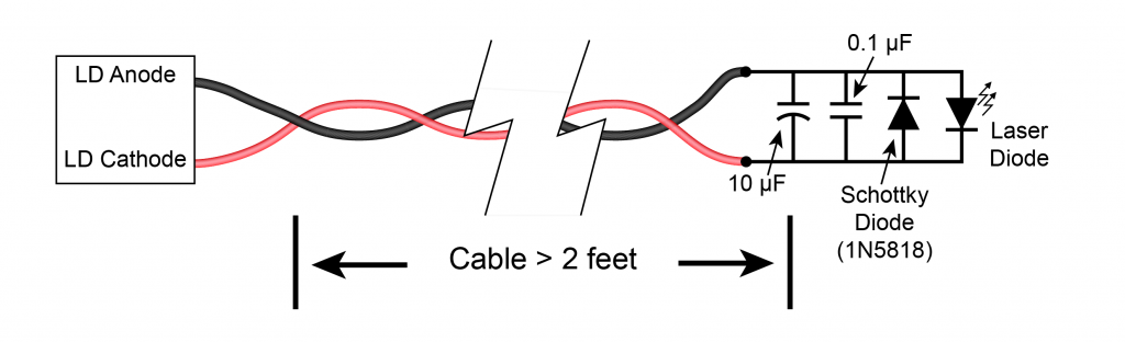
Figure 4: Long Cable Laser Protection
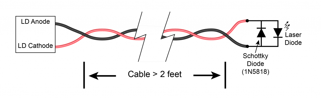
Output current may oscillate when approaching the limit setting if cables are too long. A capacitor or diode across the voltage supply and ground can be added to minimize voltage drop and noise. Figure 4 and Figure 5 show proper laser diode protection for long cables and additional noise filtering, respectively. These can help reduce reverse noise spikes and protect the load or laser.
Figure 5: Output Filter
Cable and wire companies will indicate the current carrying capacities of their products. The gauge of the wire provides a general guideline for determining expected resistances in cable connections as well as the maximum current through the wires. These specifications will change with the material used for the conductor, whether the conductor is solid or stranded, and the material of the insulation. Applications will determine the type and gauge of wires.
Solid wires are cheaper, have a more compact diameter, and a low corrosion rate. Stranded wires are more flexible and can withstand more vibration and movement. Solid wires can wear down faster from constant flexing and movement. Stranded wires are larger in diameter, more expensive, more corrosion prone, and have a higher susceptibility to electrical interference at very high frequencies due to the air in-between the strands. If the wire will be connected and disconnected many times throughout the test or application, stranded wire should be used to maintain durability during flexing and movement.
TROUBLESHOOTING TIPS
There are a few methods to reduce noise in the laser system.
- Ground properly & Shield the cables and wires
- Avoid tribo/piezoelectric sources
- Twist the wires
- Lower the current or frequency of the signal
- Separate load from the power supply
- Choose proper gauge, length to minimize resistance and inductance
- Determine electric or magnetic source of interference
All cables should be shielded to some extent to keep noise to a minimum. The source of the noise may need to be addressed and reduced if attempts to shield noise from the cables are not sufficient.
Cables should be firmly secured to avoid constant movement and friction in the conductors. This will help reduce tribo- and piezoelectric sources.
It is good practice to twist any wires, particularly from power sources, to minimize interference from sources external to the design. Twisting will reduce electromagnetic interference in the system in adjacent, current-carrying wires. Many twists will return lower radiation.
A simple way to reduce noise generation is to lower the amplitude or frequency of the signal from the driver or controller when possible. If the design allows a lower current or voltage to the load, this will decrease noise. Only the minimum amount of current and voltage should be used for powering laser diodes. It is important, when looking at products (drivers or controllers), to take note of the current and voltage levels listed when checking noise levels. For example, a laser driver operating at 2 A will generate more noise than when operating at 100 mA. Frequency, as mentioned earlier in cable shielding types, is also a major factor in increasing or decreasing noise.
Power supplies can be a large source of noise. When wiring from a power supply, twisting wires can greatly reduce noise and crosstalk. It is recommended to keep the wired device as far away from the power source as possible. This will reduce EMI in the system. However, noise from the power supply will be conducted through the cables to the controller or driver. Decreasing the original noise from the source will solve the most issues.
The application and circuitry setup will determine the proper gauge, length, and type of wire. When possible, use solid wires with shorter lengths to reduce resistance and inductance. Decreasing the diameter of the wire will increase the resistance (Ω/m) of the wire. If the wire will move throughout the application (connected and disconnected), stranded wire should be use.
To test when external noise on a cable is produced from either electric field or magnetic field sources, measure the noise voltage across the impedance at one end of the cable while decreasing the impedance at the other end. If the noise voltage decreases, the noise is electric interference. If the noise voltage increases, the noise is magnetic interference.1 Twist wires to reduce magnetic interference, and shield cables and physically move sensitive circuitry away from the noise sources (power supply).
SUMMARY
Careful consideration needs to taken for connections between sources, hardware, or electronic devices. Cables can be large sources of noise to laser or temperature designs, but the noise transmitted through them can be greatly reduced with a few simple techniques. For most low current or voltage setups, low noise is crucial to producing precise results. Shielding cables, selecting the proper materials for cables, and properly configuring wires and cables will decrease noise in the design.
The cables provided by Wavelength Electronics are specifically designed to minimize inductance by keeping the length as short as possible. Most of the cables provided by Wavelength are in the range of 10 to 36 inches in length to minimize the noise conducted. For modules, where wires are most commonly used, short wire lengths are recommended. Wavelength recommends using stranded 18 gauge wire for currents up to 5 A for the power supply and laser diode connections. For current levels greater than 5 A, stranded 14 gauge wire is recommended for Wavelength Electronic products. Most other connections usually only need 24 gauge solid core wire.
REFERENCES
- Ott, Henry W. Noise Reduction Techniques in Electronic Systems. John Wiley, 1998.
- Keithley, (2014), Low Level Measurements Handbook – 7th Edition. https://www.tek.com/document/handbook/low-level-measurements-handbook?_ga=2.26895412.804504212.1594830864-74676626.1594830864